4-16
ROUTING SWITCHER SYSTEM (E)
4-4. Basic Setup Procedures
No.
001
002
003
004
005
006
007
008
009
010
011
:
:
017
018
:
:
033
034
035
036
037
038
039
040
NAME
VTR001
VTR002
VTR003
VTR004
VTR005
VTR006
VTR007
VTR008
STU111
NEWS001
SAT001
:
:
CAM001
CAM002
:
:
DAT001
DAT002
DAT003
DIG201
DIG202
MIX201
MIX202
DIG203
VID
001-1
002-1
003-1
004-1
005-1
006-1
007-1
008-1
009-1
010-1
011-1
:
:
017-1
018-1
:
:
...-.
...-.
...-.
...-.
...-.
...-.
...-.
...-.
AUD
001-3
002-3
003-3
004-3
005-3
006-3
007-3
008-3
009-3
010-3
011-3
:
:
...-.
...-.
:
:
...-.
...-.
...-.
...-.
...-.
...-.
...-.
...-.
4
...-.
...-.
...-.
...-.
...-.
...-.
...-.
...-.
...-.
...-.
...-.
:
:
...-.
...-.
:
:
...-.
...-.
...-.
...-.
...-.
...-.
...-.
...-.
5
...-.
...-.
...-.
...-.
...-.
...-.
...-.
...-.
...-.
...-.
...-.
:
:
...-.
...-.
:
:
...-.
...-.
...-.
...-.
...-.
...-.
...-.
...-.
6
...-.
...-.
...-.
...-.
...-.
...-.
...-.
...-.
...-.
...-.
...-.
:
:
...-.
...-.
:
:
...-.
...-.
...-.
...-.
...-.
...-.
...-.
...-.
7
...-.
...-.
...-.
...-.
...-.
...-.
...-.
...-.
...-.
...-.
...-.
:
:
...-.
...-.
:
:
...-.
...-.
...-.
...-.
...-.
...-.
...-.
...-.
AES
001-2
002-2
003-2
004-2
005-2
006-2
007-2
008-2
...-.
...-.
...-.
:
:
...-.
...-.
:
:
009-2
010-2
011-2
012-2
013-2
014-2
015-2
016-2
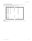
PHYSICAL NUMBER ASSIGNMENT
SOURCE LEVEL
DVS-V3232B V2.10 STATION NUMBER 1
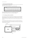
4. Physical Assignment (Menu Item [L])
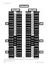
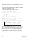
Now we actually associate the labels or names to a physical routing switcher input or output. Assign the
physical source/destination number and the physical level to the virtual source/destination name and the
virtual levels using the menu item [L : SET PHYSICAL ASSIGNMENT].
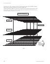
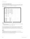
Again refer to figure 7.
m
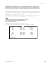
1. Create a similar table for the destination side (use F5 on the terminal setup menu [L] screen to toggle
between source/destination)
2. To delete an entry in menu item [L], press the [Ctrl] _ [P] .
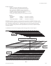
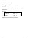
This step can be confusing because you associate the input labels with physical routing switcher inputs,
along with output labels with physical outputs. You need to tell the primary which physical X row of
crosspoints feeding an output belong with each output name or label, along with which physical Y
column of crosspoints fed by an input belong with each input name or label. To visualize, look at figures
2, 3, or 4.
n
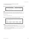
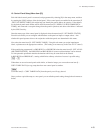
When BKPF-R70 is used as the primary station, all contents that have been set are cleared when
“A : /CLR-DATA/SBUS_LVG_DAT” which is supplied with BZR-10.
When number of items to set is smaller than number of items to clear, the procedure of clearing all items
once and setting all items from the very beginning is more efficient.


