7-11
ROUTING SWITCHER SYSTEM (E)
Z : SELECT SDI FORMAT
(DVS-V3232M/DVS-V6464M)
Purpose
This menu is used to set the format of signals fed to the
input/output board of DVS-V3232M and DVS-V6464M
with the control terminal.
This setting is available when the REM/LOC switch for the
format on each input/output board is OFF.
Setting Procedure
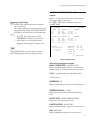
1. Select menu item “Z”.
2. Select a channel line using the cursor to be set. (The
channels will be switched by eight channels.
Displayed signal formats that are enclosed by the
round brackets as “(270 Mbps)” have been set on the
board and cannot be modified with the control termi-
nal.
3. When [Enter] is pressed, the setting will change
(“143 Mbps” → “117 Mbps” → “270 Mbps” →
“AUTO”).
4. Press [S] (Table Set), and the content now appeared is
copied to the area of SDI FORMAT TABLE.
5. Press [Ctrl] _ [E] to stop the display and return to the
menu screen of the secondary station.
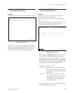
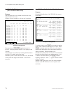
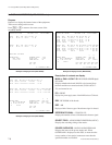
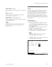
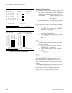
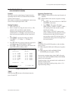
Example of Setting Screen
n
Unless pressing [S], the data will be deleted when the
power is turned off.
Operating Function Keys
[F1] : FORMAT (Mode which sets the signal format by 8-
channels)
[F2] : FIELD (Mode which sets the crosspoint switching
field)
1. Press [F2]. The cursor will move to “SWITCH
ING FIELD” in the menu.
2. Press [Enter]. The setting will change.
(ODD → EVEN → FIELD → ASYNC → ODD···)
All switching field in the switcher are deter
mined by this setting.
When a display “(ASYNC)” appears on the
screen, it indicates that the cross-point selector
field has been set in the ASYNC (asynchro-
nous) position on the CPU-149 board (S4-1). It
means that the setting cannot be changed from
the control terminal.
n
To use RS-422A and S-BUS together, set the switching
field as follows.
1 When using the S-BUS and CART protocol together :
ODD
2 When using the S-BUS and PRODUCTION
SWITCHER protocol together : FIELD
Note that the switching timing of the CART will not be
accurate if the CART and PRODUCTION SWITCHERS
protocols are used together.
Switching timing is not guaranteed in the combination of
different switching fields.
For details of the signal switching timing, refer to “5-8.
Signal Switching Timing”.
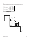
7-3. Changed Menu (Secondary Station Setting Items)
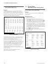
SELECT SDI FORMAT DVS-V6464M V3.00 STATION NUMBER 1
DESTINATION UNIT SOURCE UNIT
01 - 08 : 270 Mbps 01 - 08 : 270 Mbps
09 - 16 : 143 Mbps 09 - 16 : 270 Mbps
17 - 24 : 270 Mbps 17 - 24 : 270 Mbps
25 - 32 : 143 Mbps 25 - 32 : 270 Mbps
33 - 40 : 360 Mbps 33 - 40 : 270 Mbps
41 - 48 : 540 Mbps 41 - 48 : 270 Mbps
49 - 56 :( 270 Mbps ) 49 - 56 :( 270 Mbps )
57 - 64 : AUTO 57 - 64 : 270 Mbps
SWITCHING FIELD FIELD
F1:FORMAT F2:FIELD S:Table Set Ctrl-E:RETURN TO MENU


