


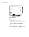
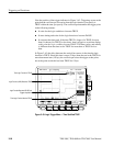
Triggering on Waveforms
TDS 500C, TDS 600B, & TDS 700C User Manual
3–77
H The Boolean logic function — select from AND, NAND, OR, and NOR
H The condition for triggering — whether the trigger occurs when the Boolean
function becomes TRUE (logic high) or FALSE (logic low), and whether the
TRUE condition is time qualified
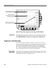
A state trigger occurs when the logic inputs to the logic function cause the
function to be TRUE (or at your option FALSE) at the time the clock input
changes state. When you use a state trigger, you define:
H The precondition for each logic input, channels 1, 2, and 3
H The direction of the state change for the clock input, channel 4
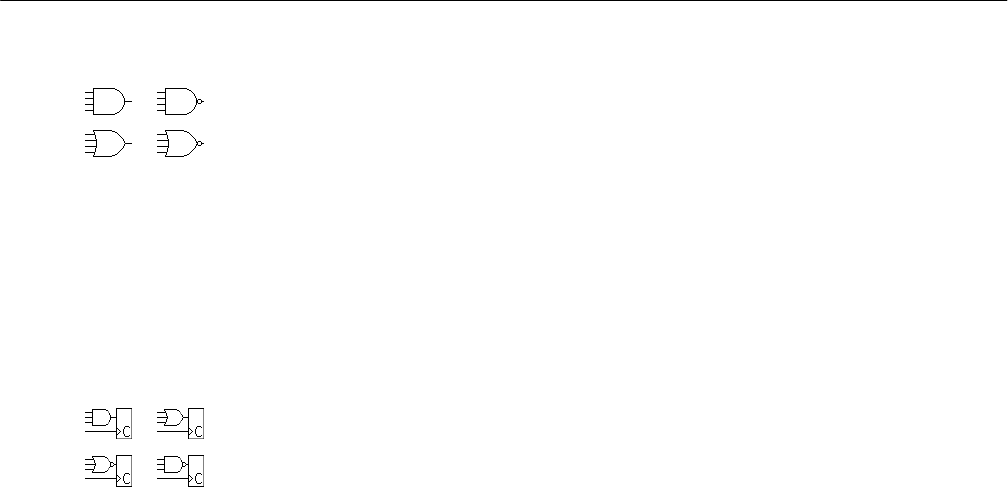
H The Boolean logic function — select from clocked AND, NAND, OR, and
NOR
H The condition for triggering — whether the trigger occurs when the Boolean
function becomes TRUE (logic high) or FALSE (logic low)
A setup/hold trigger occurs when a logic input changes state inside of the setup and
hold times relative to the clock. When you use setup/hold triggering, you define:
H The channel containing the logic input (the data source) and the channel
containing the clock (the clock source)
H The direction of the clock edge to use
H The clocking level and data level that the oscilloscope uses to determine if a
clock or data transition has occurred
H The setup and hold times that together define a time range relative to the clock
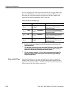
Pattern and state triggers apply boolean logic functions to the logic inputs.
Table 3–6 defines these four logic functions.
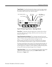
For pattern triggering, the oscilloscope waits until the end of trigger holdoff and
then samples the inputs from all the channels. The oscilloscope then triggers if
the conditions defined in Table 3–6 are met. (Goes TRUE or Goes FALSE must
be set in the Trigger When menu. The other settings in that menu are described
in To Define a Time Qualified Pattern Trigger on page 3–83.)
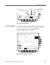
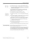
Pattern and State Classes