


Acquiring and Displaying Waveforms
TDS 500C, TDS 600B, & TDS 700C User Manual
3–17
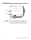
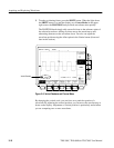
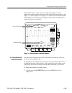
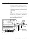
To select the coupling, bandwidth, and offset for the selected waveform, use the
Vertical menu (Figure 3–6). This menu also lets you numerically change the
position or scale instead of using the vertical knobs. To make such changes, do
the following procedures:
Coupling. To choose the type of coupling for attaching the input signal to the
vertical attenuator for the selected channel and to set its input impedance:
Press VERTICAL MENU ➞ Coupling (main) ➞ DC, AC, GND, or W (side).
H DC coupling shows both the AC and DC components of an input signal.
H AC coupling shows only the alternating components of an input signal.
H Ground (GND) coupling disconnects the input signal from the acquisition.
H Input impedance lets you select either 1 M W or 50 W impedance.
NOTE. If you select 50 W impedance with AC coupling, the digitizing oscillo-
scope will not accurately display frequencies under 200 kHz.
Also, when you connect an active probe to the oscilloscope (such as the P6245),
the input impedance of the oscilloscope automatically becomes 50 W. If you then
connect a passive probe (like the P6139A), you need to set the input impedance
back to 1 MW.
The maximum volts/div setting is reduced from 10 V to 1 V when you select 50 W
impedance. See the discussion Input Impedance Considerations on page 3–7.
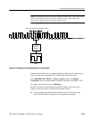
Bandwidth. Bandwidth refers to the range of frequencies that an oscilloscope can
acquire and display accurately (that is, with less than 3 dB attenuation). If you
limit the upper limit for the higher frequency components by selecting 250 MHz
or 20 MHz, a
B
W
symbol will appear in the lower part of the display. To change
the bandwidth of the selected channel:
Press VERTICAL MENU ➞ Bandwidth (main) ➞ Full, 250 MHz, or
20 MHz (side).
To Change
Vertical Parameters