


Triggering on Waveforms
TDS 500C, TDS 600B, & TDS 700C User Manual
3–87
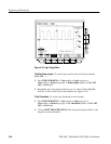
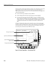
Set the Data and Clock Levels. To set the transition levels that the clock and data
must cross to be recognized by the oscilloscope:
1. Press TRIGGER MENU ➞ Type (main) ➞ Logic (pop-up) ➞
Class (main) ➞ Setup/Hold (pop-up) ➞ Levels (main) ➞ Clock Level or
Data Level (side).
2. Turn the general purpose knob or use the keypad to set values for the clock
level and for the data level you select.
If you prefer, you can set both clock levels to a value appropriate to either of two
logic families. To do so:
3. Press TRIGGER MENU ➞ Type (main) ➞ Logic (pop-up) ➞
Class (main) ➞ Setup/Hold (pop-up) ➞ Levels (main) ➞ Set Both to TTL
or Set Both to ECL (side).
The oscilloscope uses the clock level you set to determine when a clock edge
(rising or falling, depending on which you select) occurs. The oscilloscope uses
the point the clock crosses the clock level as the reference point from which it
measures setup and hold time settings.
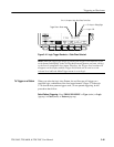
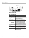
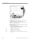
Set the Setup and Hold Times. To set the setup time and the hold time relative to
the clock:
1. Press TRIGGER MENU ➞ Type (main) ➞ Logic (pop-up) ➞
Class (main) ➞ Setup/Hold (pop-up) ➞ Set/Hold Times (main) ➞ Setup
Time or Hold Time (side). See Figure 3–44.
2. Turn the general purpose knob or use the keypad to set values for the setup
and for the hold times.
NOTE. See Setup/Hold Time Violation Trigger Minimum Clock Pulse Widths
specification in the Performance Verification and Specifications manual for valid
setup and hold times.
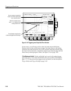
Positive setup time always leads the clock edge; positive hold time always
follows the clocking edge. Setup time always leads the hold time by at least 2 ns
(T
S
+ T
H
≥ 2 ns). Attempting to set either time to reduce the 2 ns limit adjusts the
other time to maintain the limit.