


Tutorial
2–12
TDS 500C, TDS 600B, & TDS 700C User Manual
NOTE. This manual uses the following notation to represent the sequence of
selections you made in steps 1, 2 and 3: Press save/recall SETUP ➞ Recall
Factory Setup (main) ➞ OK Confirm Factory Init (side).
Note that a clock icon appears on screen. The oscilloscope displays this icon
when performing operations that take longer than several seconds.
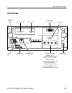
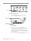
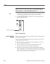
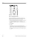
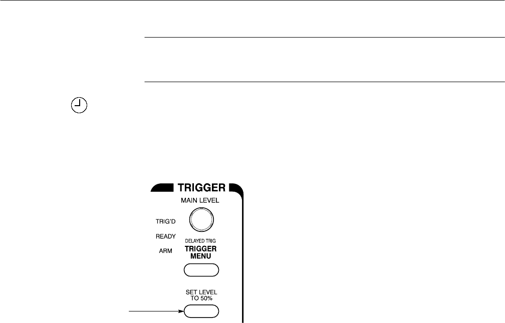
4. Press SET LEVEL TO 50% (see Figure 2–4) to be sure the oscilloscope
triggers on the input signal.
SET LEVEL TO 50% Button
Figure 2–4: Trigger Controls
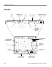
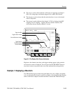
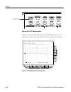
Read the following information to become familiar with the oscilloscope display
before doing the examples.
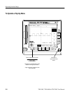
Figure 2–5 shows the display that results from the oscilloscope reset. There are
several important points to observe:
H The trigger level bar shows that the waveform is triggered at a level near
50% of its amplitude (from step 4).
H The trigger position indicator shows that the trigger position of the
waveform is located at the horizontal center of the graticule.
H The channel reference indicator shows the vertical position of channel 1
with no input signal. This indicator points to the ground level for the channel
when its vertical offset is set to 0 V in the vertical menu; when vertical offset
is not set to 0 V, it points to the vertical offset level.
Examine the Display
Elements