


Triggering on Waveforms
3–78
TDS 500C, TDS 600B, & TDS 700C User Manual
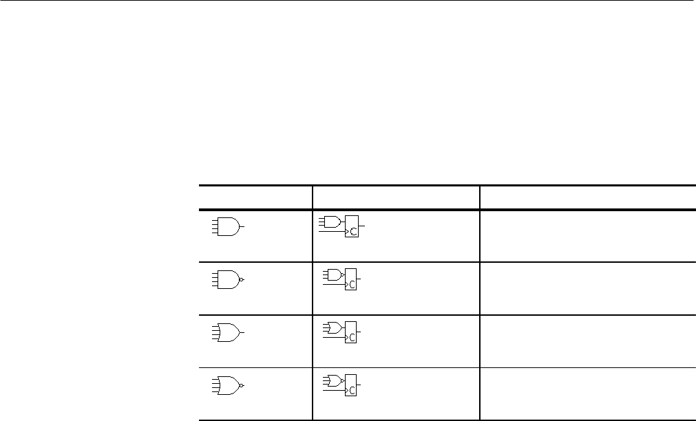
For state triggering, the oscilloscope waits until the end of trigger holdoff and
then waits until the edge of channel 4 transitions in the specified direction. At
that point, the oscilloscope samples the inputs from the other channels and
triggers if the conditions defined in Table 3–6 are met.
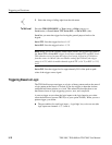
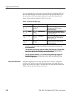
Table 3–6: Pattern and State Logic
Pattern State Definition
1,
2
AND Clocked AND If all the preconditions selected for the
logic inputs
3
are TRUE, then the
oscilloscope triggers.
NAND Clocked NAND If not all of the preconditions selected
for the logic inputs
3
are TRUE, then the
oscilloscope triggers.
OR Clocked OR If any of the preconditions selected for
the logic inputs
3
are TRUE, then the
oscilloscope triggers.
NOR Clocked NOR If none of the preconditions selected for
the logic inputs
3
are TRUE, then the
oscilloscope triggers.
1
Note that for state class triggers, the definition must be met at the time the clock
input changes state.
2
The definitions given here are correct for the Goes TRUE setting in the Trigger When
menu. If that menu is set to Goes False, swap the definition for AND with that for
NAND and for OR with NOR for both pattern and state classes.
3
The logic inputs are channels 1, 2, 3, and 4 when using pattern logic triggers. For
State Logic Triggers, channel 4 becomes the clock input, leaving the remaining
channels as logic inputs.
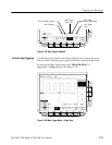
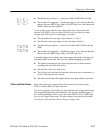
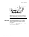
Setup/hold triggering uses the setup and hold times to define a “setup/hold
violation zone” relative to the clock. Data that changes state within this zone
triggers the oscilloscope. Figure 3–40 shows how the setup and hold times you
choose positions this zone relative to the clock.
Setup and Hold Class