Using Features for Advanced Applications
3–206
TDS 500C, TDS 600B, & TDS 700C User Manual
You specify the phase suppression level in dB with respect to 1 V
RMS
. If the
magnitude of the frequency is greater than this threshold, then its phase angle
will be displayed. However, if it is less than this threshold, then the phase angle
will be set to zero and be displayed as zero degrees or radians. (The waveform
reference indicator at the left side of the graticule indicates the level where phase
is zero for phase FFTs.)
It is easier to determine the level of phase suppression you need if you first
create a frequency FFT math waveform of the source and then create a phase
FFT waveform of the same source. Do the following steps to use a cursor
measurement to determine the suppression level:
1. Do steps 1 through 7 of To Create an FFT that begins on page 3–193. Select
dBV
RMS (side) for the Set FFT Vert Scale to (side).
2. Press CURSOR ➞ Mode (main) ➞ Independent (side) ➞ Func-
tion (main) ➞ H Bars (side). Use the general purpose knob to align the
selected cursor to a level that places the tops of the magnitudes of frequen-
cies of interest above the cursor but places other magnitudes completely
below the cursor.
3. Read the level in dB from the @: readout. Note the level for use in step
5.
4. Press MORE (main) ➞ Change Waveform Definition menu (side). Press
Set FFT Vert Scale to (side) repeatedly to choose either Phase (rad) or
Phase (deg).
5. Press Suppress Phase at Amplitudes (side). Use the general purpose knob
to set phase suppression to the value obtained using the H Bar cursor. Do not
change the window selection or you will invalidate the results obtained using
the cursor.
To learn how to optimize your display of FFT data, read about how the FFT
windows data before computing the FFT math waveform. Understanding FFT
windowing can help you get more useful displays.
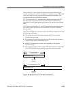
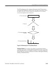
Windowing Process. The oscilloscope multiplies the FFT time domain record by
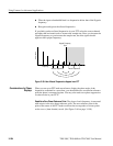
one of four FFT windows before it inputs the record to the FFT function. Figure
3–99 shows how the time domain record is processed.
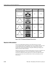
FFT Windows


