Start Up
TDS 500C, TDS 600B, & TDS 700C User Manual
1–7
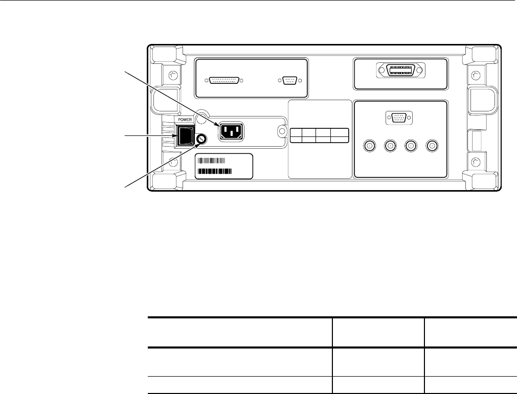
Power Connector
Principal Power Switch
Fuse
Figure 1–1: Rear Panel Controls Used in Start Up
5. Connect the proper power cord from the rear-panel power connector (see
Figure 1–1) to the power system.
Table 1–2: Fuse and fuse cap part numbers
Fuse Fuse part number
Fuse cap part
number
0.25 inch × 1.25 inch (UL 198.6, 3AG): 6 A
FAST, 250 V
159-0013-00 200-2264-00
5 mm × 20 mm (IEC 127): 5 A (T), 250 V 159-0210-00 200-2265-00
To remove the front cover, grasp the left and right edges and snap the cover off
of the front subpanel. (To reinstall the cover, align it to the front subpanel and
snap it back on.)
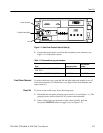
To power on the oscilloscope, do the following steps:
1. Check that the rear-panel principal power switch is on (see Figure 1–1). The
principal power switch controls all AC power to the instrument.
2. If the oscilloscope is not powered on (the screen is blank), push the
front-panel ON/STBY button to toggle it on (see Figure 1–2).
Front Cover Removal
Power On


