


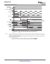
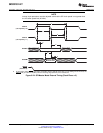
XCLKOUT
t
d(XCOH-EVASOCL)
EVASOC
t
w(EVASOCL)
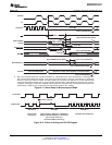
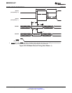
XCLKOUT
t
d(XCOH-EVBSOCL)
EVBSOC
t
w(EVBSOCL)
SM320F2812-HT
SGUS062A–JUNE 2009–REVISED APRIL 2010
www.ti.com
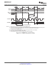
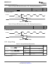
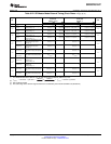
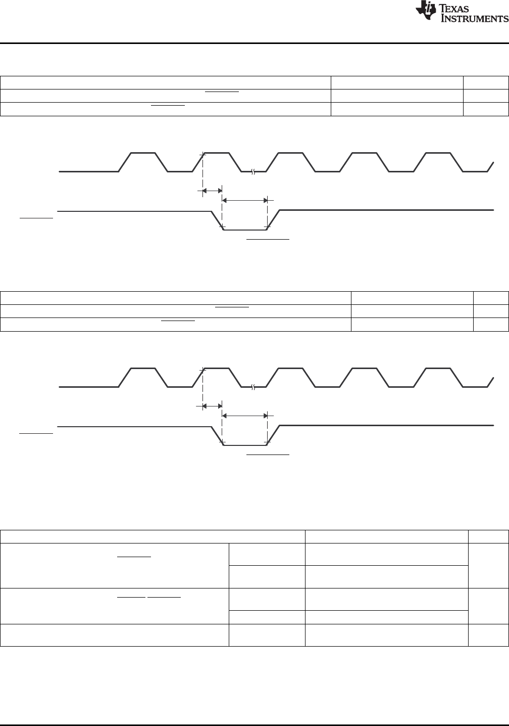
Table 6-15. External ADC Start-of-Conversion – EVA – Switching Characteristics
(1) (2)
PARAMETER MIN MAX UNIT
t
d(XCOH-EVASOCL)
Delay time, XCLKOUT high to EVASOC low 1 × t
c(SCO)
cycle
tw(EVASOCL) Pulse duration, EVASOC low 32 × t
c(HCO)
ns
(1) XCLKOUT = SYSCLKOUT
(2) Not production tested.
Figure 6-18. EVASOC Timing
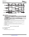
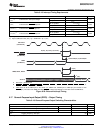
Table 6-16. External ADC Start-of-Conversion – EVB – Switching Characteristics
(1) (2)
PARAMETER MIN MAX UNIT
t
d(XCOH-EVBSOCL)
Delay time, XCLKOUT high to EVBSOC low 1 × t
c(SCO)
cycle
t
w(EVBSOCL)
Pulse duration, EVBSOC low 32 × t
c(HCO)
ns
(1) XCLKOUT = SYSCLKOUT
(2) Not production tested.
Figure 6-19. EVBSOC Timing
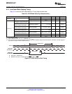
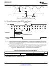
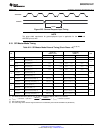
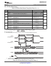
6.16.2 Interrupt Timing
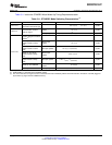
Table 6-17. Interrupt Switching Characteristics
PARAMETER MIN MAX UNIT
Without input
12
qualifier
Delay time, PDPINTx low to PWM
t
d(PDP-PWM)HZ
ns
high-impedance state
1 × t
c(SCO)
+ IQT +
With input qualifier
12
(1)
Without input
3 × t
c(SCO)
Delay time, CxTRIP/TxCTRIP signals low
qualifier
t
d(TRIP-PWM)HZ
(2)
ns
to PWM high-impedance state
With input qualifier [2 × t
c(SCO)
] + IQT
(1)
Delay time, INT low/high to
t
d(INT)
(2)
t
qual
+ 12t
c(XCO)
ns
interrupt-vector fetch
(1) Input Qualification Time (IQT) = [5 × QUALPRD × 2] × t
c(SCO)
(2) Not production tested.
106 Electrical Specifications Copyright © 2009–2010, Texas Instruments Incorporated
Submit Documentation Feedback
Product Folder Link(s): SM320F2812-HT