


XCLKIN/8
(XCLKIN * 5)
t
h(XPLLDIS)
t
h(XMP/MC)
t
h(boot-mode)
(see Note A)
t
w(RSL2)
XCLKIN
X1
XRS
XF/XPLLDIS
XMP/MC
Boot-Mode Pins
XCLKOUT
I/O Pins
Address/Data/
Control
Boot-ROM Execution Starts
User-Code Execution Starts
User-Code Dependent
User-Code Dependent
User-Code Execution Phase
(Don’t Care)
(Don’t Care)
(Don’t Care)
(Don’t Care)
User-Code Dependent
User-Code Execution
Peripheral/GPIO Function
User-Code Dependent
GPIO Pins as Input (State Depends on Internal PU/PD)
GPIO Pins as Input
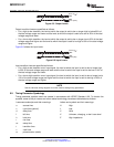
GPIOF14/XF
XPLLDIS
Sampling
GPIOF14
Peripheral/GPIO Function
t
d(EX)
t
su(XPLLDIS)
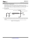
X1/XCLKIN
SYSCLKOUT
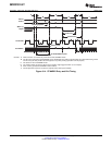
Write to PLLCR
XCLKIN x 2
(Current CPU
Frequency)
XCLKIN/2
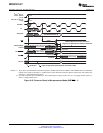
(CPU Frequency While PLL is Stabilizing
With the Desired Frequency. This Period
(PLL Lock-up Time, t
p
) is
131072 XCLKIN Cycles Long.)
XCLKIN x 4
(Changed CPU Frequency)
SM320F2812-HT
www.ti.com
SGUS062A–JUNE 2009–REVISED APRIL 2010
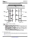
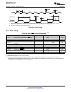
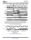
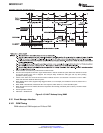
A. After reset, the Boot ROM code executes instructions for 1260 SYSCLKOUT cycles (SYSCLKOUT = XCLKIN/2) and
then samples BOOT Mode pins. Based on the status of the Boot Mode pin, the boot code branches to destination
memory or boot code function in ROM. The BOOT Mode pins should be held high/low for at least 2520 XCLKIN
cycles from boot ROM execution time for proper selection of Boot modes. If Boot ROM code executes after power-on
conditions (in debugger environment), the Boot code execution time is based on the current SYSCLKOUT speed. The
SYSCLKOUT is based on user environment and could be with or without PLL enabled.
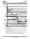
Figure 6-11. Warm Reset in Microcomputer Mode
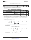
Figure 6-12. Effect of Writing Into PLLCR Register
Copyright © 2009–2010, Texas Instruments Incorporated Electrical Specifications 99
Submit Documentation Feedback
Product Folder Link(s): SM320F2812-HT