


M0 SARAM
1K x 16
CPU-Timer 0
CPU-Timer 1
INT[12:1]
CLKIN
Real-Time JTAG
CPU-Timer 2
Peripheral Bus
C28x CPU
H0 SARAM
8K ⋅ 16
INT14
NMI
INT13
Memory Bus
M1 SARAM
1K x 16
Flash
128K x 16
Boot ROM
4K ⋅ 16
eCAN
SCIA/SCIB
12-Bit ADC
External Interrupt
Control
(XINT1/2/13, XNMI)
EVA/EVB
Memory Bus
OTP
1K x 16
McBSP
System Control
(Oscillator and PLL
+
Peripheral Clocking
+
Low-Power
Modes
+
WatchDog)
FIFO
FIFO
PIE
(96 interrupts)
†
RS
SPI FIFO
TINT0
TINT1
TINT2
Control
Address(19)
Data(16)
External
Interface
(XINTF)
16 Channels
†
45 of the possible 96 interrupts are used on the device.
GPIO Pins
XRS
X1/XCLKIN
X2
XF_XPLLDIS
Protected by the code-security module.
XINT13
G
P
I
O
M
U
X
L1 SARAM
4K x 16
XNMI
L0 SARAM
4K x 16
‡
‡
‡
‡
‡
SM320F2812-HT
www.ti.com
SGUS062A–JUNE 2009–REVISED APRIL 2010
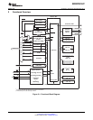
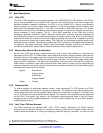
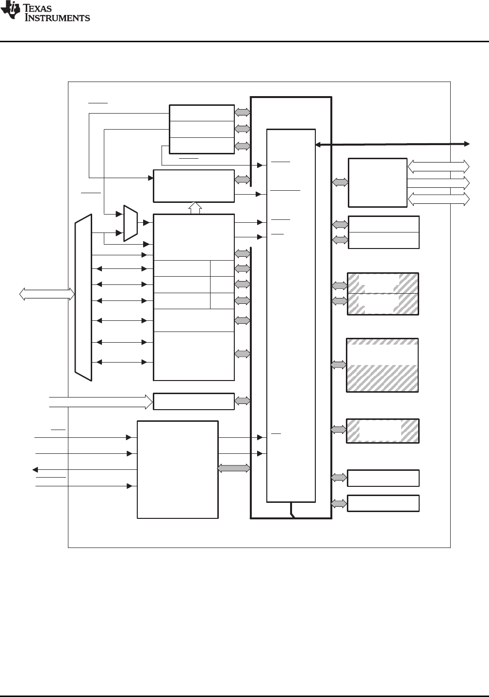
3 Functional Overview
Figure 3-1. Functional Block Diagram
Copyright © 2009–2010, Texas Instruments Incorporated Functional Overview 27
Submit Documentation Feedback
Product Folder Link(s): SM320F2812-HT