


SM320F2812-HT
www.ti.com
SGUS062A–JUNE 2009–REVISED APRIL 2010
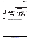
6.21 External Interface (XINTF) Timing
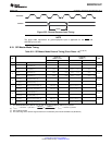
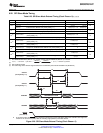
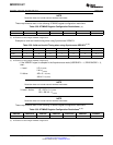
Each XINTF access consists of three parts: Lead, Active, and Trail. The user configures the
Lead/Active/Trail wait states in the XTIMING registers. There is one XTIMING register for each XINTF
zone. Table 6-25 shows the relationship between the parameters configured in the XTIMING register and
the duration of the pulse in terms of XTIMCLK cycles.
Table 6-25. Relationship Between Parameters Configured in XTIMING and Duration of Pulse
(1) (2) (3)
DURATION (ns)
DESCRIPTION
X2TIMING = 0 X2TIMING = 1
LR Lead period, read access XRDLEAD × t
c(XTIM)
(XRDLEAD × 2) × t
c(XTIM)
AR Active period, read access (XRDACTIVE + WS + 1) × t
c(XTIM)
(XRDACTIVE × 2 + WS + 1) × t
c(XTIM)
TR Trail period, read access XRDTRAIL × t
c(XTIM)
(XRDTRAIL × 2) × t
c(XTIM)
LW Lead period, write access XWRLEAD × t
c(XTIM)
(XWRLEAD × 2) × t
c(XTIM)
AW Active period, write access (XWRACTIVE + WS + 1) x t
c(XTIM)
(XWRACTIVE × 2 + WS + 1) × t
c(XTIM)
TW Trail period, write access XWRTRAIL × t
c(XTIM)
(XWRTRAIL × 2) × t
c(XTIM)
(1) Not production tested.
(2) t
c(XTIM)
– Cycle time, XTIMCLK
(3) WS refers to the number of wait states inserted by hardware when using XREADY. If the zone is configured to ignore XREADY
(USEREADY = 0), then WS = 0.
Minimum wait state requirements must be met when configuring each zone's XTIMING register. These
requirements are in addition to any timing requirements as specified by that device's data sheet. No
internal device hardware is included to detect illegal settings.
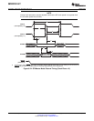
• If the XREADY signal is ignored (USEREADY = 0), then:
1. Lead: LR ≥ t
c(XTIM)
LW ≥ t
c(XTIM)
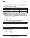
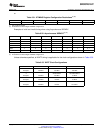
These requirements result in the following XTIMING register configuration restrictions:
Table 6-26. XTIMING Register Configuration Restrictions
(1) (2)
XRDLEAD XRDACTIVE XRDTRAIL XWRLEAD XWRACTIVE XWRTRAIL X2TIMING
≥ 1 ≥ 0 ≥ 0 ≥ 1 ≥ 0 ≥ 0 0, 1
(1) Not production tested.
(2) No hardware to detect illegal XTIMING configurations
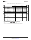
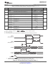
Examples of valid and invalid timing when not sampling XREADY:
Table 6-27. Valid and Invalid Timing
(1) (2)
XRDLEAD XRDACTIVE XRDTRAIL XWRLEAD XWRACTIVE XWRTRAIL X2TIMING
Invalid 0 0 0 0 0 0 0, 1
Valid 1 0 0 1 0 0 0, 1
(1) Not production tested.
(2) No hardware to detect illegal XTIMING configurations
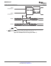
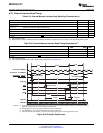
• If the XREADY signal is sampled in the Synchronous mode (USEREADY = 1, READYMODE = 0),
then:
1. Lead: LR ≥ t
c(XTIM)
LW ≥ t
c(XTIM)
2. Active: AR ≥ 2 × t
c(XTIM)
AW ≥ 2 × t
c(XTIM)
Copyright © 2009–2010, Texas Instruments Incorporated Electrical Specifications 117
Submit Documentation Feedback
Product Folder Link(s): SM320F2812-HT