


SM320F2812-HT
www.ti.com
SGUS062A–JUNE 2009–REVISED APRIL 2010
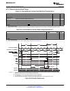
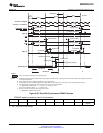
6.25 External Interface Ready-on-Read Timing With One External Wait State
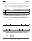
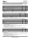
Table 6-37. External Memory Interface Read Switching Characteristics (Ready-on-Read, 1 Wait State)
(1)
PARAMETER MIN MAX UNIT
t
d(XCOH-XZCSL)
Delay time, XCLKOUT high to zone chip-select active low 1 ns
t
d(XCOHL-XZCSH)
Delay time, XCLKOUT high/low to zone chip-select inactive high –2 3 ns
t
d(XCOH-XA)
Delay time, XCLKOUT high to address valid 2 ns
t
d(XCOHL-XRDL)
Delay time, XCLKOUT high/low to XRD active low 1 ns
t
d(XCOHL-XRDH
Delay time, XCLKOUT high/low to XRD inactive high –2 1 ns
t
h(XA)XZCSH
Hold time, address valid after zone chip-select inactive high
(2)
ns
t
h(XA)XRD
Hold time, address valid after XRD inactive high
(2)
ns
(1) Not production tested.
(2) During inactive cycles, the XINTF address bus always holds the last address put out on the bus. This includes alignment cycles.
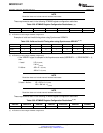
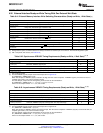
Table 6-38. External Memory Interface Read Timing Requirements (Ready-on-Read, 1 Wait State)
(1)
MIN MAX UNIT
t
a(A)
Access time, read data from address valid (LR + AR) – 14
(2)
ns
t
a(XRD)
Access time, read data valid from XRD active low AR – 12
(2)
ns
t
su(XD)XRD
Setup time, read data valid before XRD strobe inactive high 12 ns
t
h(XD)XRD
Hold time, read data valid after XRD inactive high 0 ns
(1) Not production tested.
(2) LR = Lead period, read access. AR = Active period, read access. See Table 6-25 .
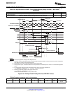
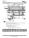
Table 6-39. Synchronous XREADY Timing Requirements (Ready-on-Read, 1 Wait State)
(1) (2)
MIN MAX UNIT
t
su(XRDYsynchL)XCOHL
Setup time, XREADY (Synch) low before XCLKOUT high/low 15 ns
t
h(XRDYsynchL)
Hold time, XREADY (Synch) low 12 ns
t
e(XRDYsynchH)
Earliest time XREADY (Synch) can go high before the sampling XCLKOUT edge 3 ns
t
su(XRDYsynchH)XCOHL
Setup time, XREADY (Synch) high before XCLKOUT high/low 15 ns
t
h(XRDYsynchH)XZCSH
Hold time, XREADY (Synch) held high after zone chip select high 0 ns
(1) Not production tested.
(2) The first XREADY (Synch) sample occurs with respect to E in Figure 6-31 :
E = (XRDLEAD + XRDACTIVE) t
c(XTIM)
When first sampled, if XREADY (Synch) is found to be high, then the access completes. If XREADY (Synch) is found to be low, it is
sampled again each t
c(XTIM)
until it is found to be high.
For each sample (n) the setup time (D) with respect to the beginning of the access can be calculated as:
D = (XRDLEAD + XRDACTIVE + n – 1) t
c(XTIM)
– t
su(XRDYsynchL)XCOHL
where n is the sample number: n = 1, 2, 3, and so forth.
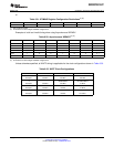
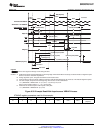
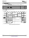
Table 6-40. Asynchronous XREADY Timing Requirements (Ready-on-Read, 1 Wait State)
(1) (2)
MIN MAX UNIT
t
su(XRDYAsynchL)XCOHL
Setup time, XREADY (Asynch) low before XCLKOUT high/low 11 ns
t
h(XRDYAsynchL)
Hold time, XREADY (Asynch) low 8 ns
Earliest time XREADY (Asynch) can go high before the sampling XCLKOUT
t
e(XRDYAsynchH)
3 ns
edge
(1) Not production tested.
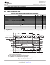
(2) The first XREADY (Asynch) sample occurs with respect to E in Figure 6-32 :
E = (XRDLEAD + XRDACTIVE – 2) t
c(XTIM)
When first sampled, if XREADY (Asynch) is found to be high, then the access completes. If XREADY (Asynch) is found to be low, it wis
sampled again each t
c(XTIM)
until it is found to be high.
For each sample, setup time from the beginning of the access can be calculated as:
D = (XRDLEAD + XRDACTIVE – 3 + n) t
c(XTIM)
– t
su(XRDYasynchL)XCOHL
where n is the sample number: n = 1, 2, 3, and so forth.
Copyright © 2009–2010, Texas Instruments Incorporated Electrical Specifications 125
Submit Documentation Feedback
Product Folder Link(s): SM320F2812-HT