TNETX4090
ThunderSWITCH II
9-PORT 100-/1000-MBIT/S ETHERNET
SWITCH
SPWS044E – DECEMBER 1997 – REVISED AUGUST 1999
2
POST OFFICE BOX 655303 • DALLAS, TEXAS 75265
description (continued)
Switching Engine
(Queue Manager)
Rambus
DRAM
Controller
VLAN 802.1Q
and
Address-Lookup Engine
2048 CAM
100/1000
MAC
GMII/PMA
Hardware
RMON
and
Etherstat
MIB
JTAG
I/F
LED
I/F
MDIO
I/F
100-M
Management
MAC
CPU I/F
With
DMA
EEPROM
I/F
10/100
MAC
MII
10/100
MAC
MII
10/100
MAC
MII
10/100
MAC
MII
10/100
MAC
MII
10/100
MAC
MII
10/100
MAC
MII
10/100
MAC
MII
Local Packet Switching Memory
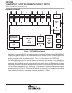
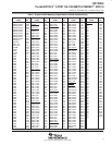
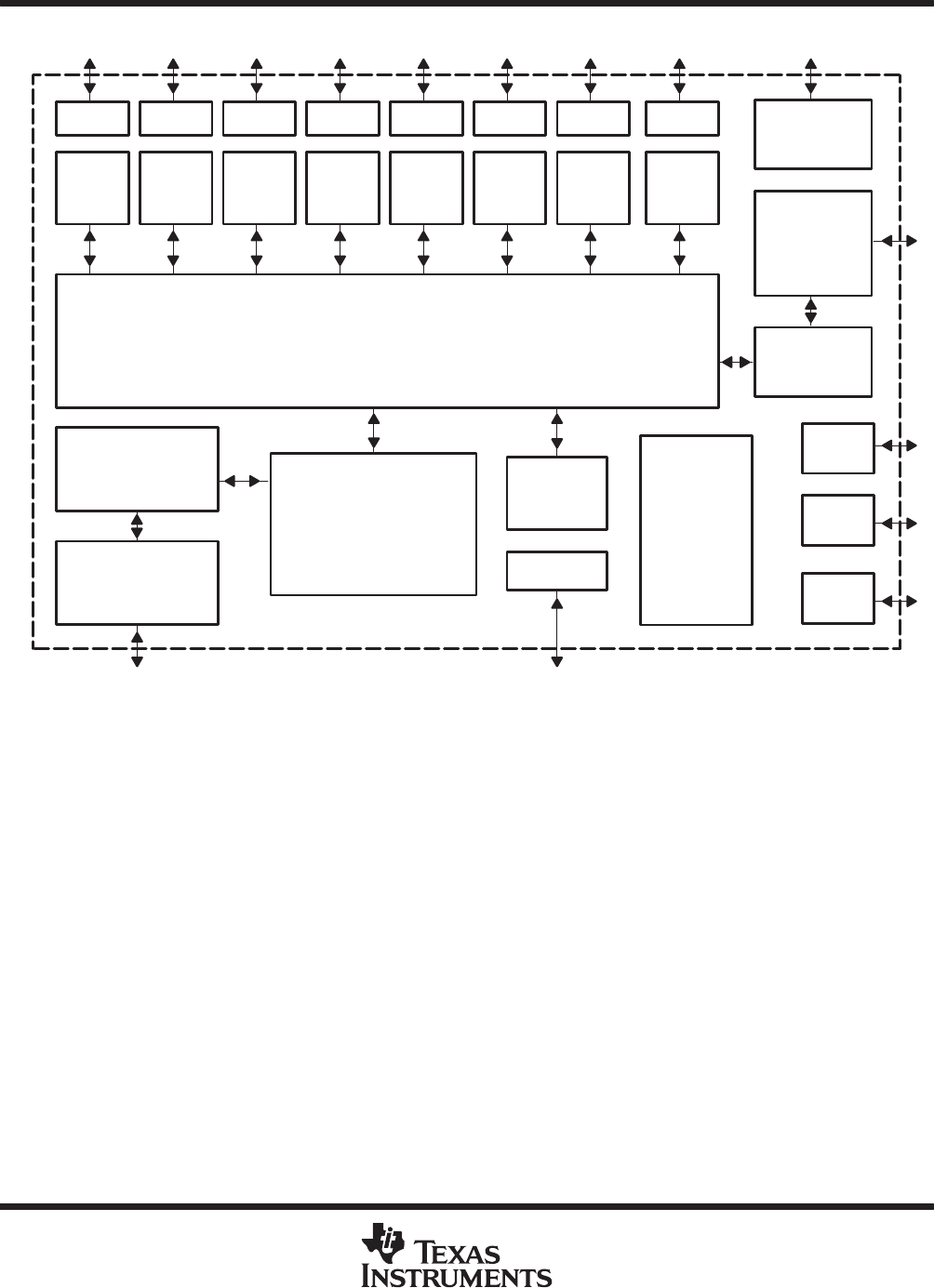
Figure 1. TNETX4090 Block Diagram
Statistics for the Etherstat, SNMP, and remote-monitoring management information base (RMON MIB) are
independently collected for each of the nine ports. Access to the statistics counters is provided via the direct
input/output (DIO) interface. Management frames can be received and transmitted via the DIO interface,
creating a complete network management solution. Figure 1 is a block diagram of the TNETX4090.
The TNETX4090 memory solution combines low cost and extremely high bandwidth, using 600-Mbit/pin/s
concurrent RDRAM. The packet memory has been implemented to maximize efficiency with the RDRAM
architecture. Data is buffered internally and transferred to/from packet memory in 128-byte bursts. Extremely
high-memory bandwidth is maintained, allowing all ports to be active without bottlenecking at the memory buffer.
The TNETX4090 is fabricated with a 2.5-V technology. The inputs are 3.3-V tolerant and the outputs are capable
of directly interfacing to TTL levels. This provides the customer with a broad choice of interfacing device options.
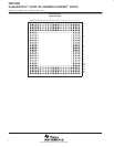
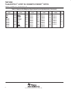
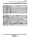
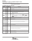
Signal names and their terminal assignments are sorted alphabetically in Table 1.


