


TNETX4090
ThunderSWITCH II
9-PORT 100-/1000-MBIT/S ETHERNET
SWITCH
SPWS044E – DECEMBER 1997 – REVISED AUGUST 1999
73
POST OFFICE BOX 655303 • DALLAS, TEXAS 75265
PARAMETER MEASUREMENT INFORMATION
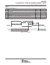
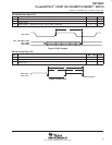
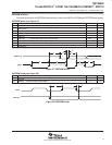
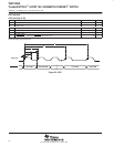
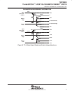
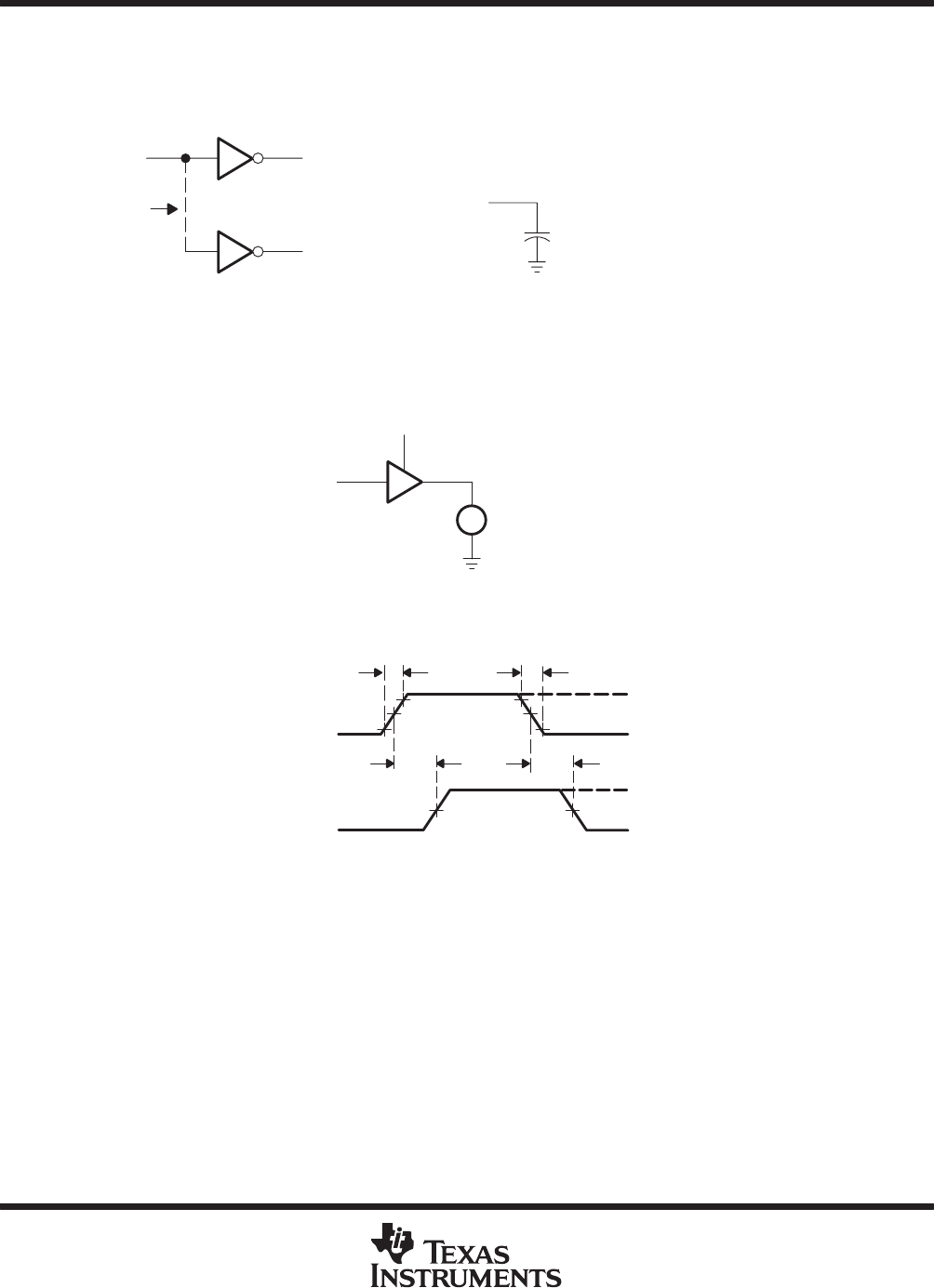
The following load circuits and voltage waveforms show the conditions used for measuring switching characteristics.
Test points are illustrated schematically on the load circuits. Reference points are plotted on the voltage waveforms.
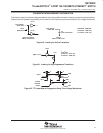
IV110
IV110
From Output
Under Test
Drive
Dependent
Internal and Input
Macro Load Circuit
From Output
Under Test
C
L
(four load values)
Output
Macro Load Circuit
t
PLH
/t
PHL
, t
PZH
/t
PZL
N channel – t
PZH
only
P channel – t
PZL
only
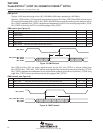
Figure 30. Loading for Active Transitions
High or Low
+ Ion
Input
t
PHZ
/t
PLZ
N channel – t
PLZ
only
P channel – t
PHZ
only
V
±
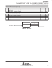
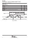
Figure 31. Loading for High-Impedance Transitions
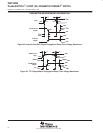
10%
90% 90%
10%
1.3 V 1.3 V
t
f
t
r
V
DD
0
Input
47%
t
PLH
V
OH
V
OL
Internal
In-Phase
Output
t
PHL
47%
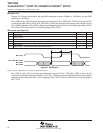
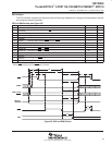
Figure 32. TTL Input Macro Propagation-Delay-Time Voltage Waveforms