


4 Replacement Procedues
4.13 Cover assembly and Base assembly
r
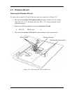
Removing the Cover assembly and Base assembly
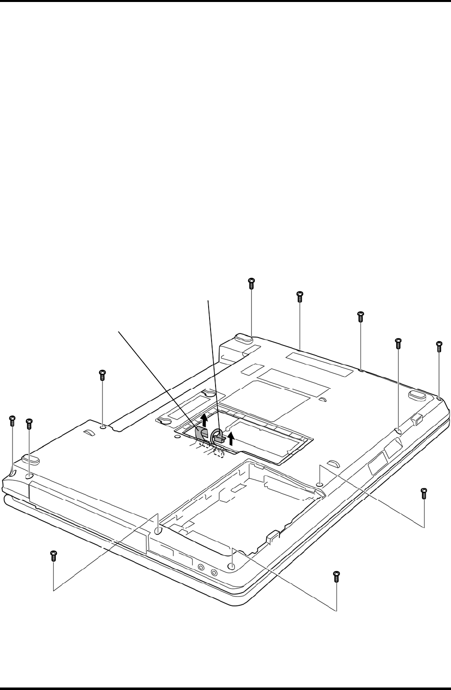
To remove the cover assembly and base assembly, follow the steps below and refer to Figure
4-23 to 4-25.
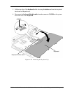
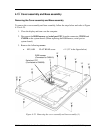
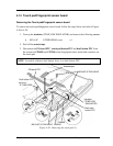
1. Close the display and turn over the computer.
2. Disconnect the RGB harness and serial port FFC from the connector CN9510 and
CN9520 on the system board. (When replacing the RGB harness, serial port or
system board.)
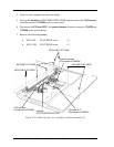
3. Remove the following screws.
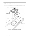
M2.58B FLAT HEAD screw 11 (“8” in the figure below)
“8”
RGB harness
(Connected to CN9510)
“8”
“8”
“8”
Serial port FFC
(Connected to CN9520)
“8”
“8”
“8”
“8”
“8”
“8”
“8”
Figure 4-23 Removing the cover assembly and base assembly (1)
TECRA A11/S11/P11 Satellite Pro S500 Series Maintenance Manual (960-784) [CONFIDENTIAL] 4-41