TMP92CM22
2007-02-16
92CM22-175
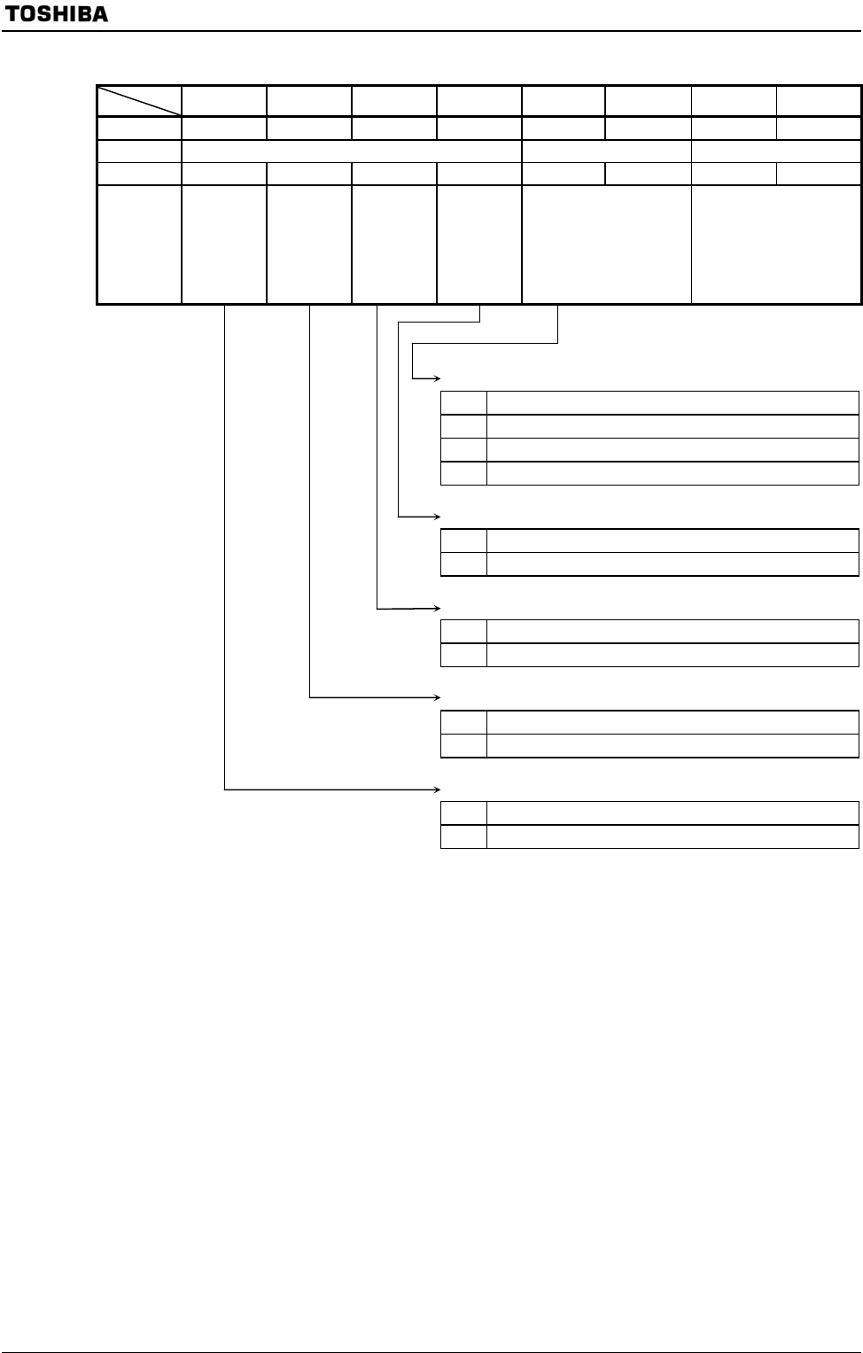
Serial Bus Interface Control Register 2
7 6 5 4 3 2 1 0
Bit symbol MST TRX BB PIN SBIM1 SBIM0 SWRST1 SWRST0SBI0CR2
(1243H)
Read/Write W W (Note 1) W (Note 1)
After reset 0 0 0 1 0 0 0 0
Read-
modify-write
instruction is
prohibited.
Function Master/
slave
selection
Transmitter/
receiver
selection
Start/stop
condition
generation
Release
INTSBE0
interrupt
request
Serial bus interface
operation mode selection
(Note 2)
00: Port mode
01: SIO mode
10: I
2
C bus mode
11: (Reserved)
Software reset control
write “10” and “01” in
order, then an internal
software reset signal is
generated.
00 Port mode (Serial bus interface output disabled)
01 Clocked-synchronous 8-bit SIO mode
10 I
2
C bus mode
11 (Reserved)
0 −
1 Release interrupt request
0 Generates the stop condition
1 Generates the start condition
0 Receiver
1 Transmitter
0 Slave
1 Master
Note 1: Reading this register function as SBI0SR register.
Note 2: Switch a mode to port mode after confirming that the bus is free.
Switch a mode between I
2
C bus mode and clocked-synchronous 8-bit SIO mode after confirming that input
signals via port are high level.
Figure 3.10.4 Register for I
2
C Bus Mode
Serial bus interface operating mode selection (Note 2)
INTSBE0 interrupt request
Start/stop condition generation
Transmitter/receiver selection
Master/slave selection


