TMP92CM22
2007-02-16
92CM22-90
3.6.4 ROM Control (Page mode)
This section describes ROM page mode accessing and how to set registers. ROM page
mode is set by the page ROM control register.
(1) Operation and how to set the registers
The TMP92CM22 supports ROM access of the page mode. ROM access of the page
mode is specified only in block address area 2.
ROM page mode is set by the page ROM control register (PMEMCR). Setting
<OPGE> of the PMEMCR register to “1” sets the memory access of the block address
area to ROM page mode access.
The number of read cycles is set by the <OPWR1:0> bit of the PMEMCR register.
OPWR1/OPWR0 Bit (PMEMCR register)
OPWR1 OPWR0 Number of Cycle in A Page
0 0 1 state (n-1-1-1 mode) (n ≥ 2)
0 1 2 states (n-2-2-2 mode) (n ≥ 3)
1 0 3states (n-3-3-3 mode) (n ≥ 4)
1 1 (Reserved)
Note: Set the number of waits (“n”) using the control register (BnCSL) in each block address
area.
The page size (The number of bytes) of ROM in the CPU side is set by the
<PR1:0> of the PMEMCR register. When data is read out up to the border of the
set page, the controller completes the page reading operation. The start data of
the next page is read in the normal cycle. The following data is set to page read
again.
PR1/PR0 Bit (PMEMCR register)
PR1 PR0 ROM Page Size
0 0 64 bytes
0 1 32 bytes
1 0 16 bytes
1 1 8 bytes
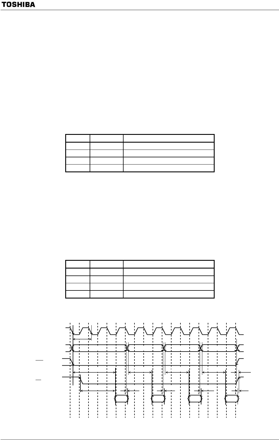
(2) Signal pulse
Figure 3.6.2 Page mode access Timing (8-byte example)
t
H
A
Data
in
p
ut
Data
in
p
ut
Data
in
p
ut
Data
in
p
ut
t
CYC
A
0 to A23
CLKOUT
D0 to D31
RD
CS2
+0
+
1
+
2 +3
t
AD3
t
AD2
t
AD2
t
AD2
t
HR
t
H
A
t
H
A
t
H
A
t
AD3


