


2
4
6
9
8
5
7
2
3
3
10
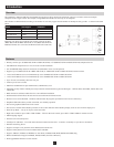
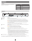
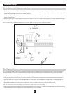
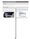
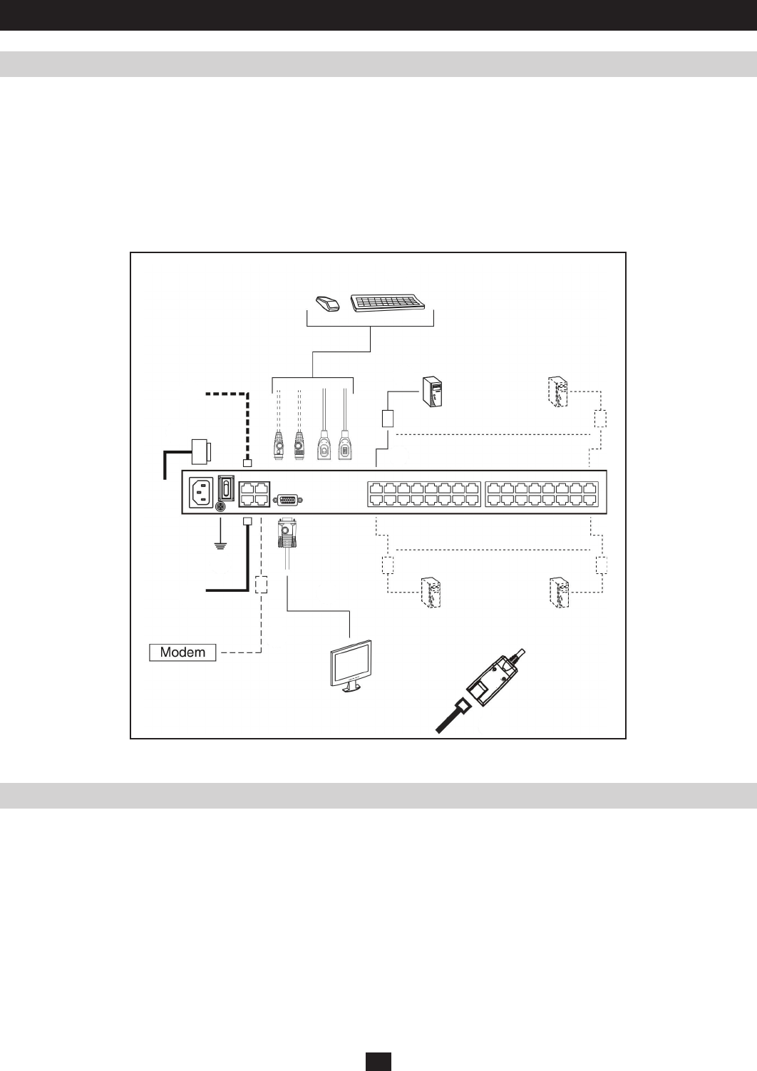
6. Optional: Connect a second Cat5e cable from the network into the KVM switch’s backup (secondary) network port (LAN 2).
7. Optional Dial-In Modem Connection: Use Cat5e cable to connect the KVM switch’s Modem port to the included RJ45 to DB9 Adapter, and
connect the adapter’s DB9 connector to the modem’s DB9 port.
8. Use the included grounding wire to ground the unit. Connect one end of the wire to the grounding terminal, and the other end of the wire to a
suitable grounded object.
9. Plug the included power cord into the KVM switch’s Power Socket, and then into a Tripp Lite Surge Suppressor, Uninterruptible Power Supply
(UPS) or PDU.
10. Turn on the power to the KVM switch. Once it is powered up, turn on the power to the connected computers.
Single Station Installation (continue d)
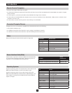
Two Stage Installations
Hardware Setup
Up to 32 additional KVM switches can be cascaded from the KVM ports of the B064- Series KVM Switch in order to expand the number of
connected computers/servers. In a cascaded installation, the top B064-Series KVM Switch is considered the First Stage unit, the cascaded
switches are considered Second Stage units.
To set up a two stage installation, refer to the instructions below:
1. Make sure that power to all the devices you will be connecting, including all pre-existing devices on the installation, have been turned off.
2. Use Cat5e patch cable to connect any available KVM Port on the First Stage unit (the B064-Series KVM Switch) to a B054-001-PS2 PS2
Server Interface Unit.
3. Plug the B054-001-PS2s KVM connectors to the Keyboard, Video, and Mouse Console ports of the Second Stage unit.
Note: The distance between the Second Stage unit and the First Stage Unit must not exceed 130 ft.
4. Use the appropriate KVM Cable Kits (See the Second Stage KVMs owner’s manual), to connect any available KVM port on the Second Stage
unit to the Keyboard, Video and Mouse ports of the computer/server you are installing.