Ithaca Peripherals Proprinter Emulation Commands
3255 4073–002 7–17
The printhead has 9 print wires, numbered from 1 to 9 with 1 being the topmost
print wire and 9 being the bottom most. Each data byte directs the activation of
the topmost 8 wires. Each data byte contains 8 data bits, numbered 0 to 7. Each
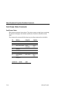
bit directs the activation of a single print wire, as shown in the following table:
Data Bit Print Wire
7 1 Top
6 2
5 3
: :
0 8 Bottom
If a data bit contains a 1, the corresponding print wire is activated when the
data byte is printed. If a data bit contains a 0, the corresponding print wire is
not activated when the data byte is printed. The same print wire must not be
activated by successive data bytes, unless the printing is single density. The
inserted byte of 0 between data bytes, in the single density case, ensures that
the same wire is not activated by successive bytes. When programming double
density graphics, you must ensure that successive data bytes do not activate the
same print wire.
Density, or horizontal resolution, is measured in dots/inch. All modes have a
vertical resolution of 72 dots/inch.
The second component of the graphics statement, number of columns, is
defined by two values, n1 and n2. To find the value of these numbers, divide the
number of columns you want to print by 256.
n1 = Remainder after dividing n by 256.
n2 = Integer after dividing n by 256.
For example to print 400 columns of graphics:
400/256 = 1 remainder 144
n1 = 144, n2 = 1


