


22
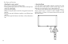
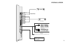
Installation
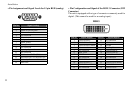
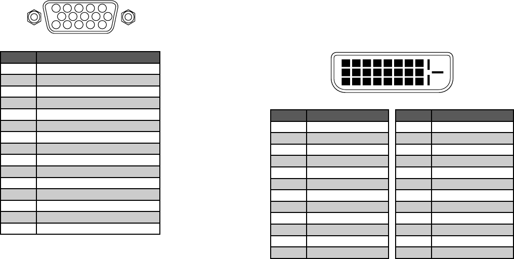
» Pin Assignment and Signal Levels for 15 pin RGB (analog) » Pin Conguration and Signal of the RGB 3 Connector (DVI
Connector)
The unit is equipped with a type of connector commonly used for
digital. (This cannot be used for an analog input.)
5 4 3 2 1
15 14 13 12 11
10 9 8 7 6
1 2 3 4 5 6 7 8
9 10 11 12 13 14 15 1
6
20191817 21 22 23 24
RGB 3
Pin No. Signal (Analog)
1 Red
2 Green or sync-on-green
3 Blue
4 No connection
5 Ground
6 Red ground
7 Green ground
8 Blue ground
9 No connection
10 Sync signal ground
11 No connection
12 Bi-directional DATA (SDA)
13 Horizontal sync or Composite sync
14 Vertical sync
15 Data clock
Pin No. Signal (Digital)
1 T.M.D.S Data 2 -
2 T.M.D.S Data 2 +
3 T.M.D.S Data 2 Shield
4 No connection
5 No connection
6 DDC Clock
7 DDC Data
8 No connection
9 T.M.D.S Data 1 -
10 T.M.D.S Data 1 +
11 T.M.D.S Data 1 Shield
12 No connection
Pin No. Signal (Digital)
13 No connection
14 +5V Power
15 Ground
16 Hot Plug Detect
17 T.M.D.S Data 0 -
18 T.M.D.S Data 0 +
19 T.M.D.S Data Shield
20 No connection
21 No connection
22 T.M.D.S Clock Shield
23 T.M.D.S Clock +
24 T.M.D.S Clock -