


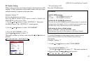
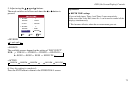

Set the ID number for the No. 1 display on ID NUMBER menu.
Perform Steps 1-2 of VIDEO WALL, then...
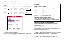
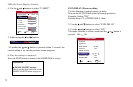
3. Use the and buttons to select “AUTO ID”.
4. Use the and buttons to select “ON”, then press the MENU
button.
The mode switches as follows each time the or button is
pressed: OFF ON
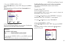
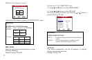
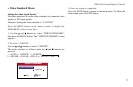
IMAGE ADJUST
The position of the image can be adjusted and ickering of the image can
be corrected.
Example: Adjusting the vertical position.
Perform Steps 1-2 of VIDEO WALL, then...
3. Use the and buttons to select “IMAGE ADJUST”, then
press the MENU button. The “IMAGE ADJUST” screen ap-
pears.
71
OSD (On Screen Display) Controls
Information
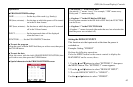
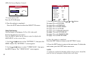
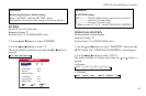
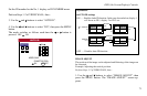
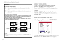
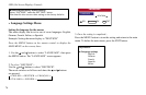
■ AUTO ID settings
ON ...... Enables Audo ID function. In the case shown below, display 1
will be set as ID 1, display 2 as ID 2, etc.
OFF ..... Disables Auto ID function.
No. 1 No. 2
No. 4 No. 3
No. 1 No. 2
No. 4 No. 3
No. 1 No. 2
No. 4 No. 3
No. 1 No. 2
No. 4 No. 3
Display 1 Display 2
Display 4 Display 3
REMOTE
IN
REMOTE
OUT
REMOTE
OUT
REMOTE
IN
REMOTE
OUT
REMOTE
IN
REMOTE
OUT
REMOTE
IN
AUTO ID
ADJ. EXIT
EXIT
CONNECTION TURN
WIRED CABLE
AUTO ID : ON
1
2
3
4
3
8
1
2
9
4
7
6
5