


Release 2.1 xi
List of Figures
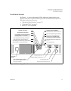
Figure 1.1 Power Supply Front Panel. . . . . . . . . . . . . . . . . . . . . . . . . . . . . . . . . . 17
Figure 1.2 Power Supply Rear Panel . . . . . . . . . . . . . . . . . . . . . . . . . . . . . . . . . . 19
Figure 1.3 Programming and Monitoring SW1 Switch . . . . . . . . . . . . . . . . . . . . . 20
Figure 1.4 Programming and Monitoring J2 Connector . . . . . . . . . . . . . . . . . . . . 22
Figure 1.5 Typical Input Current Characteristics. . . . . . . . . . . . . . . . . . . . . . . . . . 30
Figure 1.6 Dimensional Drawings. . . . . . . . . . . . . . . . . . . . . . . . . . . . . . . . . . . . . 34
Figure 2.1 Shipping or Storage Carton Label . . . . . . . . . . . . . . . . . . . . . . . . . . . . 38
Figure 2.2 AC Input Cover and Strain Relief. . . . . . . . . . . . . . . . . . . . . . . . . . . . . 42
Figure 2.3 Maximum Load Wire Length for 1 V Line Drop . . . . . . . . . . . . . . . . . . 46
Figure 2.4 Output Strain Relief and Cover . . . . . . . . . . . . . . . . . . . . . . . . . . . . . . 47
Figure 2.5 Typical Load Connection Hardware. . . . . . . . . . . . . . . . . . . . . . . . . . . 48
Figure 2.6 Output Voltage Connector . . . . . . . . . . . . . . . . . . . . . . . . . . . . . . . . . . 49
Figure 2.7 Single Load with Local Sensing (Default) . . . . . . . . . . . . . . . . . . . . . . 50
Figure 2.8 Single Load with Remote Sensing. . . . . . . . . . . . . . . . . . . . . . . . . . . . 50
Figure 2.9 Multiple Loads with Local Sensing. . . . . . . . . . . . . . . . . . . . . . . . . . . . 51
Figure 2.10 Multiple Loads with Remote Sensing. . . . . . . . . . . . . . . . . . . . . . . . . . 52
Figure 2.11 J10 Sense Connector . . . . . . . . . . . . . . . . . . . . . . . . . . . . . . . . . . . . . 54
Figure 2.12 Connecting Remote Sense Lines . . . . . . . . . . . . . . . . . . . . . . . . . . . . 56
Figure 3.1 Operating Modes . . . . . . . . . . . . . . . . . . . . . . . . . . . . . . . . . . . . . . . . . 58
Figure 3.2 Series Operation of Multiple Supplies . . . . . . . . . . . . . . . . . . . . . . . . . 66
Figure 3.3 Parallel Operation of Multiple Supplies . . . . . . . . . . . . . . . . . . . . . . . . 67
Figure 3.4 Split Supply Operation of Multiple Supplies. . . . . . . . . . . . . . . . . . . . . 68
Figure 3.5 Split Supply Operation of Multiple Supplies. . . . . . . . . . . . . . . . . . . . . 69
Figure 4.1 Connecting Programming Sources to J2 Connector . . . . . . . . . . . . . . 77
Figure 5.1 Programming and Monitoring Calibration Locations . . . . . . . . . . . . . . 81