


Installation
Load Connection
50 Operating Manual for XFR 2.8kW Series Power Supply
Inductive
Loads
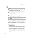
To prevent damage to the power supply from inductive kickback, connect a diode
across the output. The diode must be rated at greater than or equal to the supply’s
output voltage and have a current surge rating greater than or equal to the supply’s
output rating. Connect the cathode to the positive output and the anode to the
negative output/return.
Where positive load transients such as back EMF from a motor may occur, connect
a transorb or a varistor across the output to protect the power supply. The breakdown
voltage rating for the transorb or varistor must be approximately 10% higher than the
rated supply output.
Connecting
Single Loads
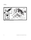
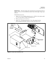
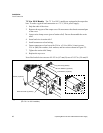
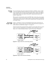
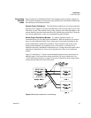
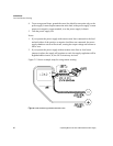
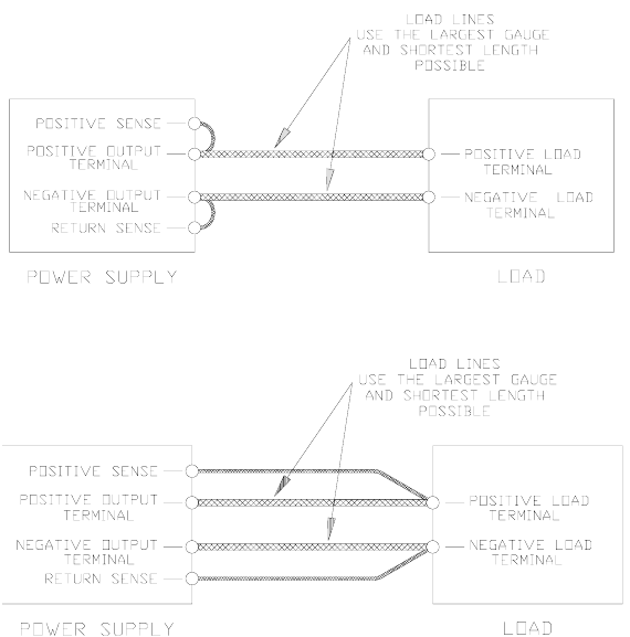
Figure 2.7 and Figure 2.8 show recommended load and sensing connections for
single loads. Local sense lines shown are default connections at the rear panel J10
sense connector as identified on Figure 1.2, on page 19.
You do not need remote sensing for basic operation of your supply. However, if you
wish to correct any small drops in your load lines, then use the remote sensing
feature. See “Local and Remote Sensing” on page 53 for more information.
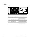
Figure 2.7 Single Load with Local Sensing (Default)
Figure 2.8 Single Load with Remote Sensing