Installation
Load Connection
48 Operating Manual for XFR 2.8kW Series Power Supply
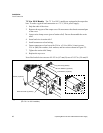
7.5 V to 100 V Models The 7.5 V to 100 V models are equipped with output bus
bars. To make a typical load connection to a 7.5 V, 300 A power supply:
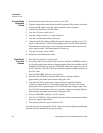
1. Strip the ends of the wires.
2. Remove the top part of the output cover. Do not remove the chassis-mounted part
of the cover.
3. Loosen wire clamp screws (part of strain relief). Do not disassemble the strain
relief.
4. Insert load wire in strain relief.
5. Install connectors to load wiring.
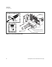
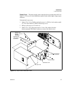
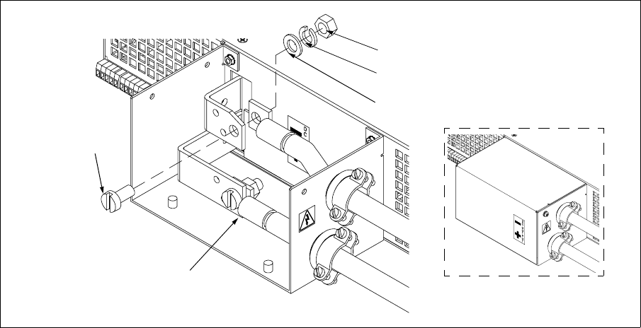
6. Fasten connectors to bus bars with 5/16 in. x 5/8 in. (M8 x 16 mm) screws,
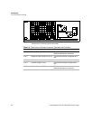
5/16 in. (M8) flat washers, lock washers, and hex nuts as shown in Figure 2.5.
7. Tighten the strain relief clamp.
8. Replace the top cover.
Note: Bus bar hole sizes are one of 0.343 in. (8.7 mm) D; two of 0.197 in. (5.0 mm) D.
Figure 2.5 Typical Load Connection Hardware
(For 7.5 V to 100 V models.)
Hex Nut (2 places)
Lock Washer (2 places)
Flat Washer (2 places)
Screw (2 places)
Wire connector (2 places)
Assembled View


