


Installation
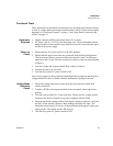
Functional Tests
Release 2.1 43
Functional Tests
These functional test procedures include power-on and front panel function checks
as well as voltage and current mode operation checks. Refer to front and rear panel
diagrams in “Front Panel Controls” on page 17 and “Rear Panel Connectors and
Switch” on page 18.
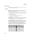
Equipment
Required
• Digital voltmeter (DVM) rated better than 0.5% accuracy.
• DC shunt 1 mV/A (±0.25%) with connecting wire. The recommended current
ratings for the DC shunt and the wire must be at least 10% more than the output
current of the power supply.
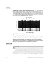
Power-on
Check
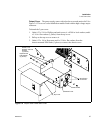
1. Ensure that the AC power switch is in the OFF position.
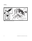
2. Ensure that the output sense lines are connected in the default configuration.
(The local sense lines are connected between terminals 1 and 2 and between
terminals 4 and 5 on the J10 sense connector as shown on the rear panel diagram
in Figure .)
3. Turn the voltage and current controls fully counter-clockwise.
4. Connect the unit to an AC outlet.
5. Turn the front panel AC power switch to ON.
After a short, power-on delay, the front panel digital meters light up and the green
voltage mode LED turns on. Both voltmeter and ammeter displays read zero.
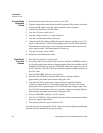
Voltage Mode
Operation
Check
1. Ensure the voltage and current controls on the front panel are turned fully
counter-clockwise.
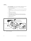
2. Connect a DVM to the output terminals on the rear panel, observing correct
polarity.
3. Turn the current control a 1/2-turn clockwise. Slowly turn the voltage control
clockwise and observe both the front panel voltmeter and the DVM.
4. Compare the DVM reading with the front panel voltmeter reading to verify the
accuracy of the internal voltmeter. Both readings should be the same. The
minimum control range is from zero to the maximum rated output for the power
supply model. The voltage mode LED turns on.
5. Turn the front panel AC power switch to OFF.