


Installation
AC Input Power
Release 2.1 41
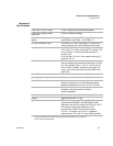
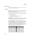
Cord The AC input cord we recommend is specified in Table 2.3, “AC Wire
Specification”. Add a non-locking plug suitable for use in the country in which you
are operating. If you require a special cord, call us.
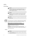
Table 2.3 AC Wire Specification
AC Input Wire
Connection
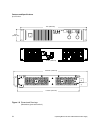
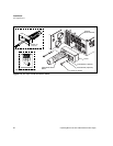
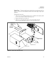
1. Strip the outside insulation on the AC cable approximately 4 in. (10 cm). Trim
the wires so that the ground wire is 0.5 in. (12 mm) longer than the other wires.
Strip 0.55 in. (14 mm) at the end of each of the wires. See Figure 2.2 detail (top).
2. Unscrew the base of the strain relief from the helix-shaped body. Insert the base
through the outside opening in the AC input cover and, from the inside, screw
the locknut securely onto the base.
3. Slide the helix-shaped body onto the AC cable. Insert the stripped wires through
the strain relief base until the outer cable jacket is flush with the edge of the base.
Tighten the body to the base while holding the cable in place. The cable is now
securely fastened inside the strain relief.
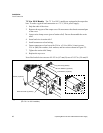
4. Route the AC wires to the input connector terminals as required. For input
connector terminal locations, see lower inset in Figure 2.2. To connect the
wiring, loosen the terminal screw, insert the stripped wire into the terminal, and
tighten the screw securely.
5. Route the wires inside the cover to prevent pinching. Fasten the AC input cover
to the unit using the (6-32 x 1 1/4 in. (2)) screws, flat washers, and lock washers
provided. See Figure 2.2.
Wire Size Ratings Cable Outside Diameter
3 x 12 AWG stranded copper 60 °C minimum, 300 V 0.545-0.708 in.
(13.63-17.7 mm)
WARNING
Ensure that the chassis ground screw does not penetrate more than 3/8 in.
(9 mm) into the rear panel of the unit.