


Installation
Load Connection
46 Operating Manual for XFR 2.8kW Series Power Supply
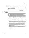
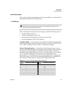
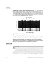
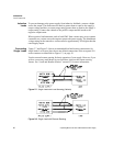
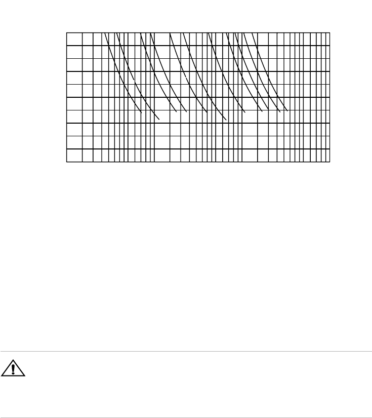
Load Wiring Length for Operation with Sense Lines For applications using
remote sensing, you must limit the voltage drop across each load wire. Figure 2.3
shows some maximum allowable wire lengths for a given load current and wire size.
We recommend that you use the larger load wiring to ensure a smaller voltage drop
(1 V typical maximum), although units will compensate for up to 5 V drop in each
line. See also “Local and Remote Sensing” on page 53.
)
Figure 2.3 Maximum Load Wire Length for 1 V Line Drop
Noise and Impedance Effects To minimize noise pickup or radiation, use
shielded pair wiring of the shortest possible length for load wires. Connect the shield
to the chassis via a rear panel mounting screw. Where shielding is impossible or
impractical, simply twisting the wires together will offer some noise immunity.
When using local sense connections, use the largest practical wire size to minimize
the effects of load line impedance on the regulation of the supply.
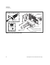
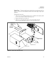
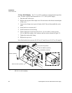
Making Load
Connections
Make load connections at the rear of the power supply at the positive and negative
output bus bars or to the 4-terminal wire clamp connector, depending on the model.
WIRE GAUGE (AWG)
16
14
12
10
8
6
4
2 1/0
1 2/0
WIRE LENGTH (FEET)
100
90
80
70
60
50
40
30
20
10
LOAD CURRENT (AMPS)
1
2
3
4
5
6
7
8
9
10
20
30
40
50
60
70
80
90
100
200
300
400
500
1000
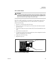
!
CAUTION
When making connections to the bus bars, ensure that each terminal's mounting
hardware and wiring assembly are placed to avoid touching the other terminal
and shorting the power supply output. Heavy connecting cables must have some
form of strain relief to avoid loosening the connections or bending the bus bars.