


Features and Specifications
Specifications
Release 2.1 33
Mechanical
Specifications
Front Panel V and I Control 10-turn voltage and current potentiometers
Front Panel Voltage Control
Resolution
0.02% of maximum voltage
Front Panel Voltage and Current
Meters
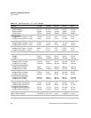
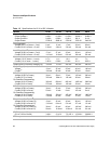
3.5-digit green numeric LED displays. For accuracy
specifications, see Table 1.4 and Table 1.5.
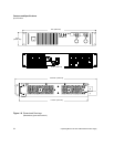
AC Input Connector Type 3-terminal 34 A, 250 V, right angle, PC mount, wire
clamp connector with removable strain relief cover
Input Fuses
1
1 A, 250 V, 5 x 20 mm slow fuse (T), location: F34;
1.5 A, 250 V, 5 x 20 mm time delay (T), location: F33;
20 A, 250 Vac, 5 x 20 mm fast high interrupt (F),
location: F36;
30 A, 300 Vac, 10.3 x 41.3 mm medium time lag (T),
locations: F2, F3.
Output Connector 7.5 V to 100 V models: nickel-plated copper bus bars
with removable bus bar shield; bus bar holes: 0.343 in.
(8.7 mm) diameter (D) (1), 0.197 in. (5.0 mm) D (2);
150 V to 600 V models: 4-terminal, right angle, PC
mount, wire clamp connector with removable strain
relief cover.
Sense Connector 5-terminal wire clamp connector (2 piece)
Analog Programming Connector 15-terminal wire clamp connector (2 piece)
Chassis Ground One chassis ground screw located on rear panel for
bonding connections or for wire shield grounding.
Maximum penetration into unit is 0.375 in. (9 mm).
Cooling Fan cooled. Air exhausts to rear. Over temperature
shutdown: automatic restart or latch off
(switch-selectable).
Mounting Rack mount brackets. Mount at front panel.
Weight Approximately 33lb. (15 kg)
Approvals CE-marked units are approved to IEC 1010-1 safety
standard and EN50081-2 and EN500082-2 EMC
standards, and are CSA certified to C22.2 No. 1010.1.
CE-marked units are also approved to U.S.
requirements of NRTL/C and are UL listed to
UL3111-1, 1st edition, (up to 40 °C). Additional
standards met: FCC, part 15, class A EMI standard.
1. Fuses are located on the A4 PCB (printed circuit board). The fuses are
NOT operator-replaceable.