


Local Operation
Using Over Voltage Protection (OVP)
Release 2.1 61
Using Over Voltage Protection (OVP)
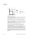
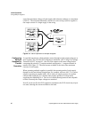
The OVP circuit protects the load in the event of a remote programming error, an
incorrect voltage control adjustment, or a power supply failure. The protection
circuit monitors the output voltage at the output of the power supply and will shut
down the main power converter whenever a preset voltage limit is exceeded. Set the
preset voltage limit (also called the set point or trip level) using the
screwdriver-adjustable, front panel OVP potentiometer, or via one of the optional
GPIB or RS-232 programming interfaces.
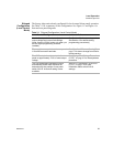
Notes:
1. The default preset limit is approximately 110% of the rated output voltage.
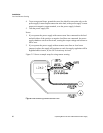
2. When using OVP with remote sensing lines connected, compensate for the
voltage line drop across the output return line by measuring or calculating the
line drop, then adding this value to the desired OVP setpoint.
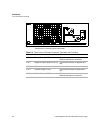
Front Panel
OVP
Operation
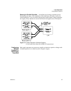
In local control mode, check the OVP set point at any time by pressing the OVP
CHECK switch. The OVP set point is the value displayed on the digital voltmeter.
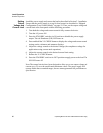
To set the trip level from the front panel:
1. Disconnect any loads. Turn the power supply ON.
2. Adjust the power supply output voltage to any voltage lower than the desired trip
level.
3. Press the front panel STANDBY (output shutdown) switch to its IN position.
The red S/D LED
turns on.
4. Press the OVP CHECK switch to see the OVP set point on the voltmeter display.
5. Holding down the OVP CHECK switch, turn the OVP SET potentiometer until
the desired set point is reached. Release the OVP CHECK switch.
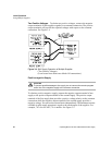
6. Press the STANDBY switch to its OUT position. The S/D LED turns off.
7. To check that the power supply shuts off at the desired set point, slowly increase
the output voltage while monitoring the front panel voltmeter. The OVP LED on
the front panel turns on when the OVP circuit activates.