


Features and Specifications
Rear Panel Connectors and Switch
Release 2.1 19
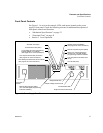
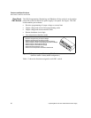
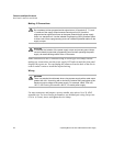
Figure 1.2 Power Supply Rear Panel
(Low voltage (7.5 V to 100 V) model shown.)
Blank Subplate
(Replaced if digital
programming interface
installed.)
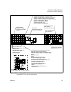
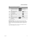
SW1 Switch (See page 20 for more information.)
1 Resistive Programming of Output Voltage
2 Resistive Programming of Output Current Limit
3 Output Voltage Programming Source Range
4 Output Current Limit Programming Source Range
5 Output Voltage Monitor Range
6 Output Current Monitor Range
7 Remote Shutdown Logic
8 Over Temperature Reset Mode
DC Output
(See inset and page 45
for more information.)
Fan Exhaust Vents
(Do not block.)
AC Input Connector
(See page 40
for more information.)
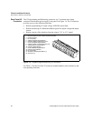
J10 Sense Connector
(See page 53 for more information.)
1 Return Sense
2 Negative Output (Return)
3 No connection (N/C)
4 Positive Output
5 Positive Sense
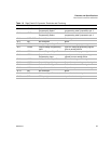
J2 Programming and Monitoring Connector
(See page 22 for more information.)
1 Remote Output Voltage Programming Select
2 Remote Output Current Limit Programming
Select
3 Control Ground
4 N/C
5 Voltage Program Signal Return
6 Output Voltage Program Input
7 Current Program Signal Return
8 Output Current Limit Programming Input
9 Voltage Monitor Signal Return
10 Output Voltage Monitor
11 Current Monitor Signal Return
12 Output Current Monitor
13 N/C
14 Shutdown (S/D) Signal Return (–)
15 S/D Input (+)
Output Voltage Connector
For high voltage (150 V to 600 V) models.
Chassis Ground Screw
(3/8 in (9 mm) maximum
penetration into unit.)