


Dimension ES-3124 Ethernet Switch
Hardware Connections 3-1
Chapter 3
Hardware
Connections
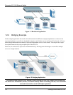
This chapter acquaints you with the front and rear panels, shows you how to make the connections,
install/remove (optional) modules and explains the LEDs.
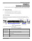
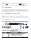
3.1 Safety Warnings
The length of exposed (bare) power wire should not exceed 7mm.
Do not use this product near water, for example, in a wet basement.
Only a qualified technician should service or disassemble this device.
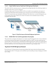
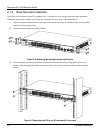
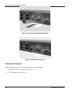
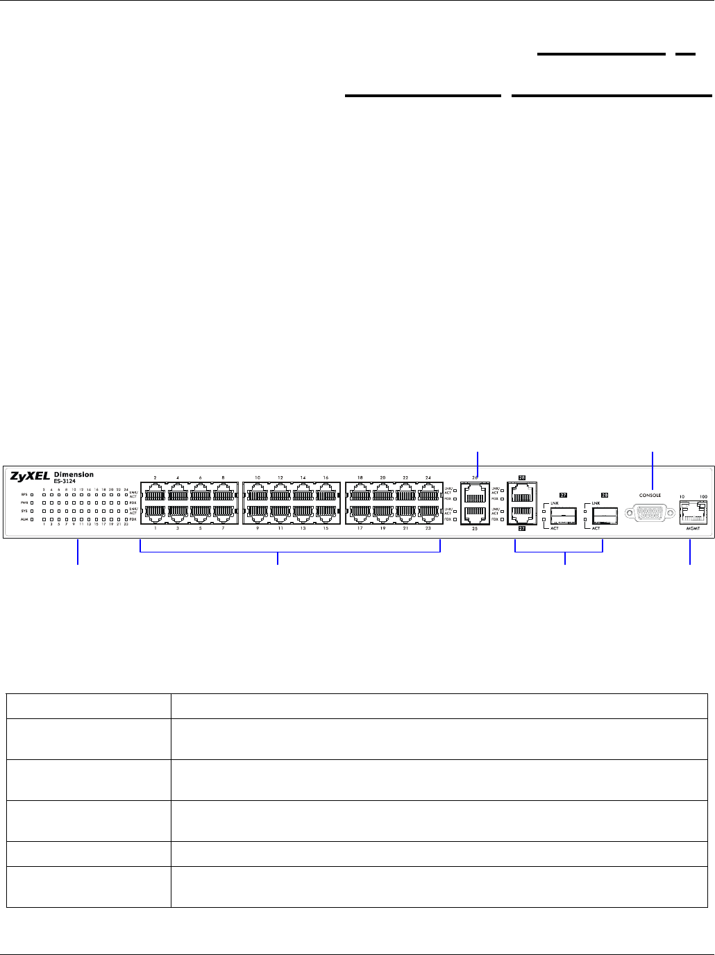
3.2 Front Panel
The following figure shows the front panel of the ES-3124. The front panel contains switch LEDs, 24 RJ-45
Ethernet ports, four RJ-45 Gigabit ports, 2 mini GBIC ports, and a console port and a management port for local
switch management.
Figure 3-1 ES-3124 Front Panel
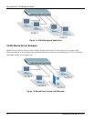
The following table describes the ports on the front panel.
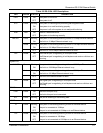
Table 3-1 ES-3124: Front Panel Ports
CONNECTOR DESCRIPTION
24 10/100 Mbps RJ-45
Ethernet connectors
Connect these ports to a computer, a hub, an Ethernet switch or router.
Four 100/1000 Mbps
RJ-45 Gigabit Ports
Connect these 1Gbps Ethernet ports to high-bandwidth backbone network Ethernet
switches or use them to daisy-chain other switches.
Two Mini GBIC Ports Use mini GBIC transceivers in these slots for fiber-optical connections to backbone
Ethernet switches.
Console Port The console port is for local configuration of the switch.
Management Port Connect to a computer using an RJ-45 Ethernet cable for local configuration of the
switch.
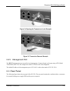
Ethernet Ports
RJ-45 Gigabit / Mini GBIC
Combo Ports for uplink
LEDs
Management Port
Console Port
RJ-45 Gigabit Ports for stacking