


Dimension ES-3124 Ethernet Switch
3-6 Hardware Connections
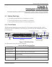
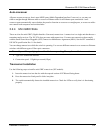
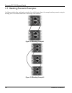
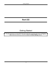
Figure 3-6 ES-3124 Rear Panel
3.3.1 Power Connector
Make sure you are using the correct power source as shown on the panel.
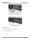
To connect the power to the ES-3124, insert the female end of power cord to the power receptacle on the rear panel.
Connect the other end of the supplied power cord to a 100~240VAC/1.5A power outlet. Make sure that no objects
obstruct the airflow of the fans (located on the side of the unit).
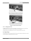
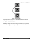
3.3.2 External Backup Power Supply Connector
The switch supports external backup power supply (BPS).
The backup power supply constantly monitors the status of the internal power supply. The backup power supply
automatically provides power to the switch in the event of a power failure. Once the switch receives power from the
backup power supply, it will not automatically switch back to using the internal power supply even when the power
is resumed.
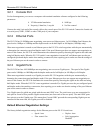
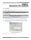
3.4 Front Panel LEDs
After you connect the power to the switch, view the LEDs to ensure proper functioning of the switch and as an aid
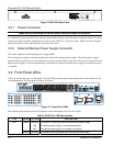
in troubleshooting. The front panel LEDs are as follows.
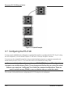
Figure 3-7 Front Panel LEDs
The following table describes the LED indicators on the front panel of an ES-3124 switch.
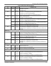
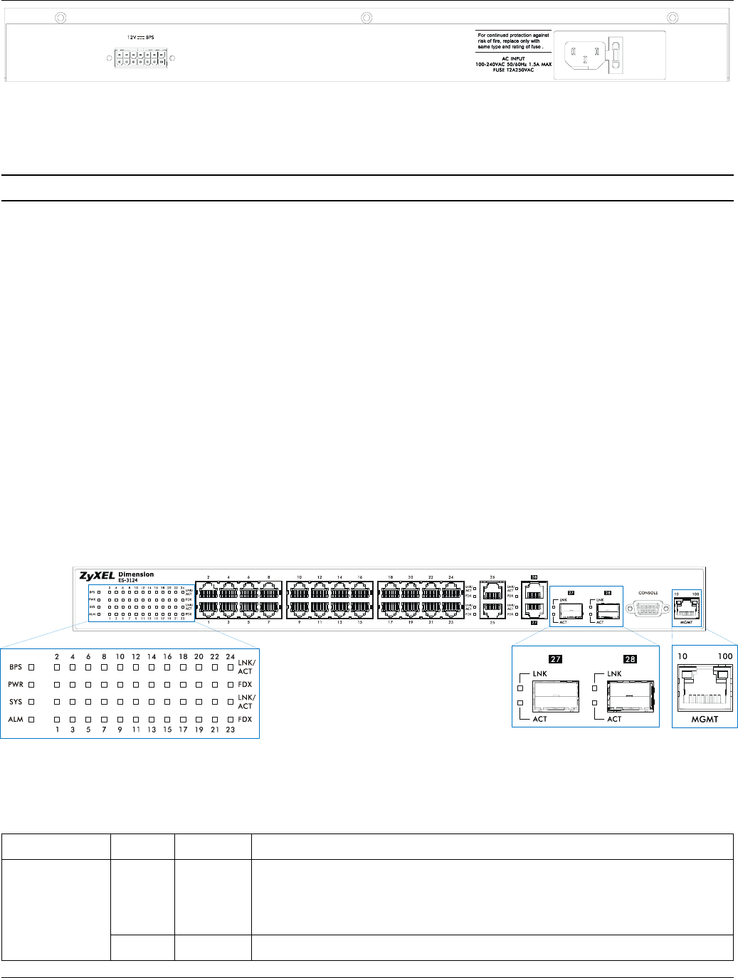
Table 3-2 ES-3124: LED Descriptions
LED COLOR STATUS DESCRIPTION
Green Blinking
ON
OFF
The system is receiving power from the backup power supply.
The backup power supply is connected and active.
The backup power supply is not ready or not active.
BPS
Amber Blinking The system cannot get power from the backup power supply.