


ZyWALL 5/35/70 Series User’s Guide
Chapter 7 WAN Screens 128
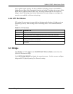
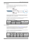
7.4.1.1 Example 1
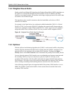
The following figure depicts an example where both the WAN ports on the ZyWALL are
connected to the Internet. The configured available outbound bandwidths for WAN 1 and
WAN 2 are 512K and 256K respectively.
Figure 47 Least Load First Example
If the outbound bandwidth utilization is used as the load balancing index and the measured
outbound throughput of WAN 1 is 412K and WAN 2 is 198K, the ZyWALL calculates the
load balancing index as shown in the table below.
Since WAN 2 has a smaller load balancing index (meaning that it is less utilized than WAN 1),
the ZyWALL will send the subsequent new session traffic through WAN 2.
Table 30 Least Load First: Example 1
INTERFACE
OUTBOUND
LOAD BALANCING INDEX
(M/A)
AVAILABLE (A) MEASURED (M)
WAN 1 512 K 412 K 0.8
WAN 2 256 K 198 K 0.77
7.4.1.2 Example 2
This example uses the same network scenario as in Figure 47 on page 128, but uses both the
outbound and inbound bandwidth utilization in calculating the load balancing index. If the
measured inbound stream throughput for both WAN 1 and WAN 2 is 102K, the ZyWALL
calculates the average load balancing indices as shown in the table below.
Since WAN 1 has a smaller load balancing index (meaning that it is less utilized than WAN 2),
the ZyWALL will send the next new session traffic through WAN 1.
Table 31 Least Load First: Example 2
INTERFACE
OUTBOUND INBOUND
AVERAGE LOAD
BALANCING INDEX
(OM / OA + IM / IA) / 2
AVAILABLE
(OA)
MEASURED
(OM)
AVAILABLE
(IA)
MEASURED
(IM)
WAN 1 512 K 412 K 256 K 102 K ( 0.8 + 0.4) / 2 = 0.6
WAN 2 256 K 198 K 128 K 102 K ( 0.77 + 0.8 ) / 2 = 0.79