Aastra CNX hardware
2-6 ATP-CNX-040-01 Rel. 1.3, Doc. Rev. 01.07
CNX System Administrator Guide
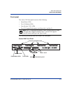
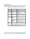
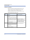
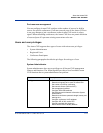
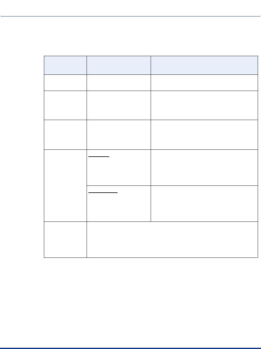
The following table describes each of the components on the Aastra CNX front
panel.
Front Panel
Component
State Meaning
Power LED OFF
ON (green)
Power off
Power on
Status LED OFF
ON (green)
ON (red)
ON (red) for 1 second
Power off
Ready to take calls
Alarm condition
Normal condition at bootup
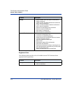
ENET LEDs
(1, 2)
OFF
ON (green)
FLASH (green)
No link present
Link present and online: normal operating
condition
Rx/Tx activity
T1/E1 LEDs
(Pairs 1, 2, 3, 4)
Top LED
OFF
ON (green)
No link provisioned or link in alarm status
Link present and online with no errors or
alarms detected
Bottom LED
OFF
ON (amber)
ON (red)
No link provisioned or no alarm
Physical link is in yellow alarm state.
Physical link is in red alarm state.
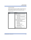
Slot 1/Slot2 Slots to accept a CompactFlash memory card.
Note: One (1) CompactFlash memory card is included with the Aastra
CNX unit and is shipped installed in slot 1. Aastra CNX supports
True IDE mode, and Type I and Type II cards.


