


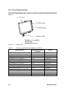
A-2 Maintenance Data
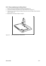
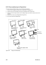
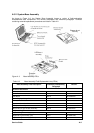
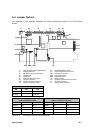
A.3.1 Cover-Display Assembly
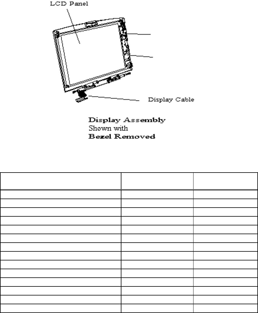
The Cover-Display Assembly shown in Figure A-2, contains the LCD screen, DC-AC Inverter Board
Logic, DC-DC Inverter Board Logic, bezel LCD cover and various other components as listed in
Table A-1.
Figure A- 2 Display FRUs
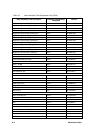
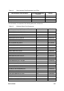
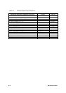
Table A-1 Top Cover Assembly Field-Replaceable Units (FRUs)
FRU Description Assembly/Disassembly
Paragraph
Part No.
LCD Panel, 12.1", DSTN 6.5.22 56.07469.071
LCD Panel, 12.1", TFT 6.5.22 56.07530.011
Display Back Cover, 12.1" 6.5.22
Display Bezel for 12.1", DSTN LCD 6.5.20 41.46913.001
Display Bezel for 12.1", TFT LCD 6.5.20 41.47003.001
LCD ID Board for 12.1", DSTN LCD 6.5.21 19.21018.111
LCD ID Board for 12.1", TFT LCD 6.5.21 19.21018.121
LCD Inverter for 12.1", TFT/DSTN LCD 6.5.21 19.21026.041
Display Cable Assembly, for 12.1", DSTN LCD 6.5.22 50.46915.021
Display Cable Assembly, for 12.1", TFT LCD 6.5.22 50.48405.021
LCD Screw Cover Left Ref 47.46907.001
LCD Screw Cover Right Ref 47.46904.001
Left Hinge Ref 34.46909.001
Right Hinge Ref 34.46919.001
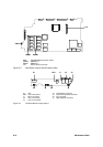
LCD ID Board
LCD Inverter