


Service Guide A-7
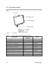
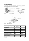
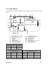
A.4. Jumper Options
The remainder of this appendix describes the jumper configuration options for the 670 Series
boards.
J1 External PS/2 mouse/keyboard port J15 CD-ROM/FDD connector
J4 External CRT port J17 Power supply board connector
J5 Expansion port (port replicator) CN1 LED board connector
J2 Parallel port SW2 CPU speed switch
J3 Serial port SW1 Password switch
J6 FIR/audio board connector J16 HDD connector
J8 Charger connector J14 Keyboard transfer board connector
J10 DC-DC converter connector J11 PC Card connector
J12 Debug card golden finger J7 Display cable connector
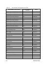
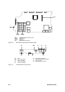
Password Switch (SW1)
SW1 ON OFF
switch 1 bypass check
switch 2 - reserved
CPU Speed Switch (SW2)
CPU Core Voltage
(Switch on DC-DC converter))
SW2 150 MHz 166 MHz 3.1V 2.9V
switch 1 ON OFF switch 1 OFF ON
switch 2 OFF ON switch 2 OFF ON
switch 3 ON ON switch 3 OFF OFF
switch 4 ON ON switch 4 ON OFF
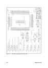
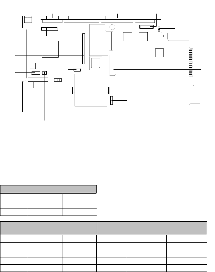
Figure A- 4 Main Board Jumper Options (top side)
J1 J4 J5 J2 J3 J6
SW1 SW2 CN1 J17
J7
J11
J14
J16
J10
J12
J15
J8