


3 System upgrade
48
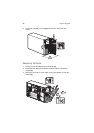
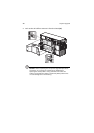
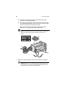
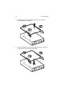
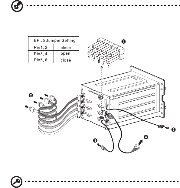
(3) Attach the system’s power cable to the SATA power cable
connector on the backplane (4).
(4) Attach the SATA backplane SAF-TE cable to the JP3 connector
on the backplane (5), then connect the other end of the cable
to the I
2
C connector on the RAID controller.
Refer to the illustration below when installing the SATA
backplane, or removing and replacing the cables.
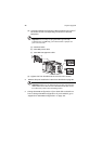
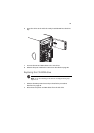
Note: The SATA RAID backplane data cables must be installed and
removed in the following order: SATA0, SATA1, SATA2, and
SATA 3.
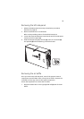
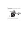
5 Observe the post-installation instructions described on page 40.
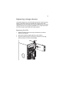
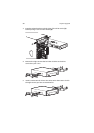
Important: When you are detaching the hot-plug cage from the
chassis, make sure to first remove all hard disks from their carriers.
For instructions, refer to the succeeding section.