


Chapter 3 51
Disassembly Procedure Flowchart
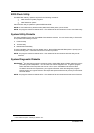
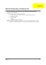
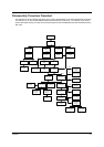
The flowchart on the succeeding page gives you a graphic representation on the entire disassembly sequence
and instructs you on the components that need to be removed during servicing. For example, if you want to
remove the system board, you must first remove the keyboard, then disassemble the inside assembly frame in
that order.
Start
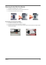
Battery Pack
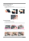
2 Middle
Covers
Keyboard
Ax1
Ax3
Cx2
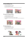
DIMM Cover
Wireless LAN
Module
Black & White
RF Cable
DIMM
Coaxial Cable
Ax2
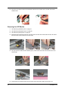
LCD Module
Ax4
DIMM Upper
Plate
Cx2
Button Board
Main Unit LCD Bezel
Ax3
Inverter Board
Ax2
Ax2
Auxiliary
Antenna
LCD W/
Protection
Cover
Main Antenna
Dx2
Dx1
Ex2
Ax4
LCD Panel
Ax8
Upper Case
LCD Support
Knobs
Touch Pad
Module
Touch Pad
FPC
RTC Battery
Ax2
Main Board
Ax4
Gx4
PCMCIA
Socket
Heat Sink /
VGA Plate
LCD HInges
W/ Center
Hinge
Ax2
Lower Case
Modem Board
Sensor Board Coaxial Cable
Video Capture
Kit Covers
HDD Module
HDD CaseHDD
HDD
Connector
Bx1
HDD Cover
Speaker
Fx2
Ax4
Ax2
Hx3