Total Access 1240 Installation and Maintenance Practice
3-10 61179605L5-5B
Alarm Connections
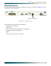
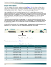
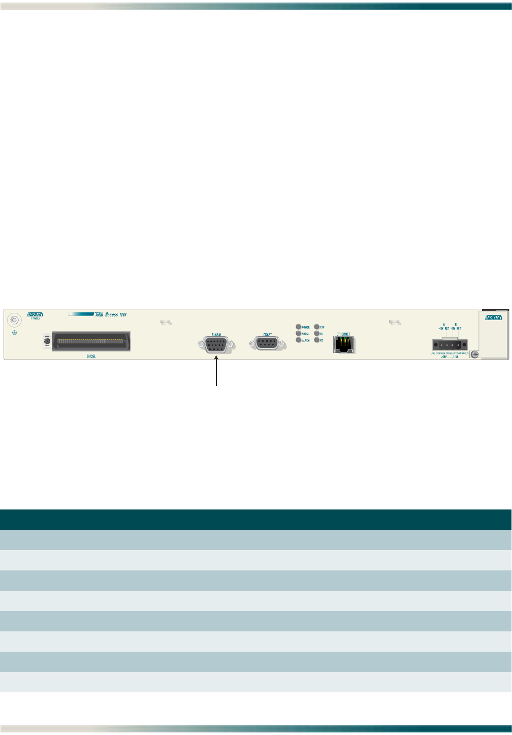
The Total Access 1240 provides an alarm port (see Figure 3-8) with three auxiliary alarm
inputs and three alarm outputs. Alarm inputs are activated by shorting A and B contacts
which causes an alarm event. Alarm input events can be configured to one of four modes:
Load Shedding, Major, Minor, or Critical and can be designated by the user.
Load shedding can be used to reduce loading in the CO if needed. When invoked, load
shedding causes the unit to switch off sealing current and drops the SHDSL loops to eliminate
power consumption in the product. This can be controlled by one of the external alarm inputs
and is automatically activated by the unit if the internal temperature of the unit reaches
115°C. When the units internal temperature decreases to 110°C it returns to normal
operation.
The alarm outputs provide both normally open and normally closed pins (through internal
relay contacts) for proper operation with a variety of alarm panels. Each alarm event generates
an autonomous message that is transmitted through the management VLAN channel to a
monitoring device.
A cable with a high density DB-15 female connector on one end and a stub at the other end is
available (P/N 1196DB901L1) for wire-wrap connections to an alarm panel.
Figure 3-8. Alarm Connection
The alarm pinouts are shown in Table 3-2.
Table 3-2. Alarm Pinouts
Pin Contact Description Pin Contact Description
1 Alarm 3 Input - A 9 Minor Alarm NC
2 Alarm 1 Input - B 10 Major Alarm NC
3 Critical Alarm COM 11 Alarm 2 Input - B
4 Minor Alarm COM 12 Alarm 1 Input - A
5 Major Alarm COM 13 Critical Alarm NO
6 Alarm 3 Input - B 14 Minor Alarm NO
7 Alarm 2 Input - A 15 Major Alarm NO
8 Critical Alarm NC
Alarm Connection


