18
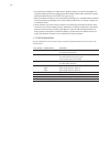
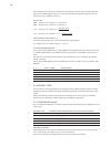
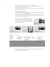
The prerequisite for a set point to infl uence the total set point value is that it must be enabled by
the set point Enable Register. Set point 1 and 2 can be linked using the following functions. The
result of this link is called set point (1,2).
Set point link
ADD Set point (1,2) = Set point 1 + Set point 2
IADD Set point (1,2) = Set point 1 - Set point 2
_Pro Set point (1,2) = Set point 1 *
Set point 2 [%]
100%
_IPro Set point (1,2) = Set point 1 * (1 -
Set point 2 [%]
)
100%
VALUE RANGE OF SET POINT (1,2)
For the link result of set point (1,2) the following value range applies:
0
ͨ Set point (1,2) ͨ Set point max (U
max
, I
max
, P
max
).
SET POINT ENABLE REGISTER
The set point Enable Register (AD_P_SW_ENABLE, adr. 94) enables the 4 set points to be shut off
or enabled independently. Only enabled set point inputs are part of the effective total set point
value.
The shut off or inactive set points are shown by the LBA and can thus, if necessary, be checked
before connecting.
The set point Enable Register can be changed from all service units (Bus, Thyro-Tool Familiy, LBA).
Example:
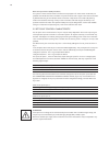
8 4 2 1 VALUE ABBR. EXPLANATION
1 1 1 1 15 STD Standard (all ON)
1 0 0 0 8 LOC Motor poti-set point 4 (LOCAL)
0 1 0 0 4 REMOTE Bus set point 3
0 0 1 1 3 ANA Analog-set points 1,2
0 0 0 0 0 All set points inactive
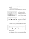
2.3 CONTROL TYPES
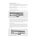
Thyro-P has fi ve control types effective as underlying controls. Mains voltage variations and load
changes are directly and therefore quickly adjusted by bypassing of the slow temperature control
system.
Before commissioning of the Power Controller and selection of a control type, you should be
familiar with the operating procedure respectively the effect for application.
2.3.1 CONTROLLED VALUE
The controlled value effective on the load is proportionate to the total set point, depending on the
control type:
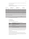
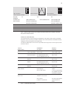
CONTROL TYPE CONTROL VALUE (PROPORTIONATE TO THE TOTAL SET POINT)
P control output (active) power, P
U control output voltage, U
rms
U
2
control output voltage, U
2
rms
I control output current, I
rms
I
2
control output current, I
2
rms
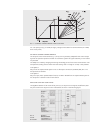
LIMITING OF SIGNALS
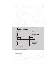
Independent of the control type set, additionally minimum and maximum limiting values may be
set. For this purpose, also refer to Fig. 1 control characteristic.
The maximum limiting values determine the maximum modulation of the load.


