


57
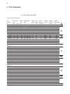
When using the ASM option, the analog output 2 (X5.2.33 against ground X5.1.13) becomes an
output proportionate to the current during the on-period T
S
. All Power Controllers connected to
synchronization work on the same external burden. The burden resistor is calculated approximately
as
R
burden
[k⍀] = 10V / (n x 20mA) n = number of Power Controller
The burden voltage is measured at the ASM input. The Power Controller searches within the clock
control the place with the lowest mains load.
Due to this automated, independent procedure, the process chain is ensured through the tempe-
rature control circuit and the Power Controller without effects; negative effects like fl icker and sub-
harmonics of the mains frequency are balanced out during a current dynamic process. In this case,
unfavorableshort-term overlapping may occur, for instance after set point jumps or voltage swing.
The application document ASM-procedure gives further information on this.
A
D
A
D
A
D
A
D
Power
Controller 1
total burden
twisted/shielded
U
burden
= ( I
1
+...+ I
n
) x R
burden
U
burden
= 0-10 volts
Power
Controller 2
0-20mA
Iact. val. 2
U
burden
0-20mA
ASM input
Iact. val. 2
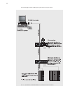
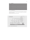
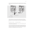
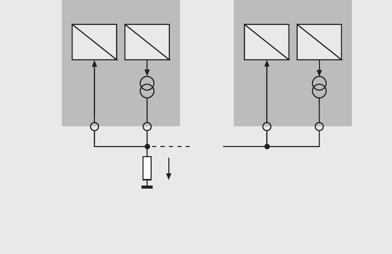
FIG. 20 ASM WIRING
X5.2.16
X5.2.33
X5.1.13
process the controller requires an ASM control device. An additional burden resistor is used for all
controllers. Schematic wiring of Power Controllers for the ASM process can be seen in the following
illustration:
ASM input