28
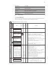
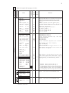
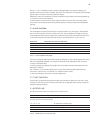
Parameters
Remarks
Main menu
= Main menu (appears after plugging in the LBA)
Submenu
Menu
next
submenu
Default
Value
User
Value
Act. val. select
Analog outp.(32)
Parameterization for analog output 1, terminal 32
Analog outp.(33) 3
Parameterization for analog output 2, terminal 33
Analog outp.(34)
Parameterization for analog output 3, terminal 34
Display top
Parameterization for operation display, value top
Display middle 4
Parameterization for operation display, value middle
Display bottom
Parameterization for operation display, value bottom
Average xx 25
Mean value analog display of xx mains/cycle periods
Graphics 5 Parameterization line diagram
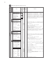
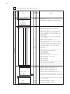
Analog outp.(32)
3 Analog outp.(33)
Analog outp.(34)
Analog outp.(xx)
Selected analog output 1,2,3 (terminal 32,33,34)
Select and OK
Selection of (if ecisting in the Power Controller):
U1, I1, P1, PG U1(32) U1, I1, P1, PG
U2, I2, P2 I1(33) U2, I2, P2
U3, I3, P3, alpha P1(34) U3, I3, P3, alpha, total set point
U3, I3, P3, set point Display total set point
U
min
,I
min
,P
min
Minimum and maximum values of U, I, P since
U
max
,I
max
,P
max
last RESET respectively voltage startup.
Current output OFF,ON Changeover 10V/20mA
Full scale xx,xmA Measuring device end scale deflection e.g. 20mA
Offset 0mA
Offset signal for output value, for instance 4mA
Full scale value xxx y
Y=dimension depending on display V, A, kW
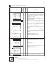
Display top
4 Display middle
Display bottom
Display
Operation display: top, middle, bottom (3 values)
Select and OK
Selection of (if ecisting in the Power Controller):
U1, I1, P1, PG U1, I1, P1, PG
U2, I2, P2 U2, I2, P2
U3, I3, P3, alpha U3, I3, P3, alpha, total set point
U3, I3, P3, set point Display total set point
U
min
,I
min
,P
min
Minimum and maximum values of U, I, P since
U
max
,I
max
,P
max
last RESET respectively voltage startup.
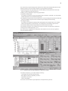
5 Line diagram
X - axis - time Scaling of the time axis (resolution pixels)
1,5min;30min;1h;3h
1.5min
Y - axis - value
Selection of (if existing in the Power Controller type):
U1, I1, P1, PG U1 U1, I1, P1, PG (resolution 50 pixels)
U2, I2, P2, alpha U2, I2, P2, alpha,
U3, I3, P3, set point U3, I3, P3, total set point,
Start graphic Start line diagram
bar, average value
Display band (all measured values) or average value
limitations Presets limiting values
U
rms
max
xxxxV type Display/default
(at 3P default setting phase voltage)
I
rms
max
xxxxA type Display/default
P
max
xxxxkW type Display/default
op. time
max
xxxxms 1000ms
Only for the operating modes TAKT and SSSD (< T
o
)
Ft.
Imp End
xxx°e 180 Only for the operating mode VAR
Rr.
Imp End
xxx°e 0 Only for VAR
on. time
min
xxxxms * 0
U
rms
min
xxxxV * 0
I
rms
min
xxxxA * 0
P
min
xxxxkW * 0
Phase swingL xxx 0 Phase swing for L1, L2, L3
* password protection


