


45
V116
V116
V132
V132
V114
V114
C137
C137
X30
X30
X31
X31
X24
X24
X10
X10
V112
V112
X507
X507
V281
V281
V261
V261
V271
V271
K3
K3
K2
K2
K1
K1
X508
X508
G800
G800
X222
X222
X221
X221
X201
X201
X510
X510
X509
X509
H405
H405
H404
H404
H403
H403
H402
H402
H401
H401
H400
H400
V700
V700
V220
V220
T101
T101
H101
H101
H102
H102
H104
H104
P8
P8
P7
P7
R125
R125
V600
V600
X700
X700
X603
X603
X702
X702
X701
X701
R147
R147
R101
R101
X800
X800
H106
H106
S101
S101
H103
H103
H105
H105
X1
X1
X706
X706
X707
X707
X713
X713
X602
X602
X703
X703
X503
X503
X502
X502
X501
X501
S102
S102
BR806
BR806
BR807
BR807
BR155
BR155
BR808
BR808
X5.1
5
10
11
32
33
34
16
17
12
15
18
19
20
5
10
11
32
33
34
16
17
12
15
18
19
20
5
13
13
13
13
13
13
21
14
14
14
14
20
1
2
X7.1 (-)
X7.2 (+)
35
33
31
25
23
21
15
13
11
36
34
26
24
22
16
14
12
32
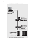
External power supply
X6
42
41
33
32
31
23
22
21
13
12
11
+5V output
setpoint 1
setpoint 2
analog output 1
analog output 2
ASM input
pulse lock
controller lock
SYT 9
acknowledgement
+24V output
function
analog output 3
GND 24V, open=blocked
GND 24V, open=blocked
for poti, etc.
M 5V setpoint 1
GND 5V, 0-20mA, 10V
GND 5V
-3,3V
M 24V
GND 24V, short circuit
+24V
application reference
GND 5V, 0-20mA, 10V
GND 5V, 0-20mA, 10V
ground temp. sensor
input temp. sensor
thyristor L3 neg
+3,3V
thyristor L2 neg
+3,3V
thyristor L2 pos
thyristor L3 pos
thyristor L1 neg
+3,3V
thyristor L1 pos
load voltage L3
sync L3
current transformer L3
load voltage L2
current transformer L2
load voltage L1
sync L1
sync L2
current transformer L1
X 5.2
signal
M 5V setpoint 2
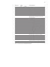
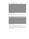
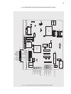
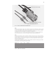
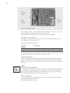
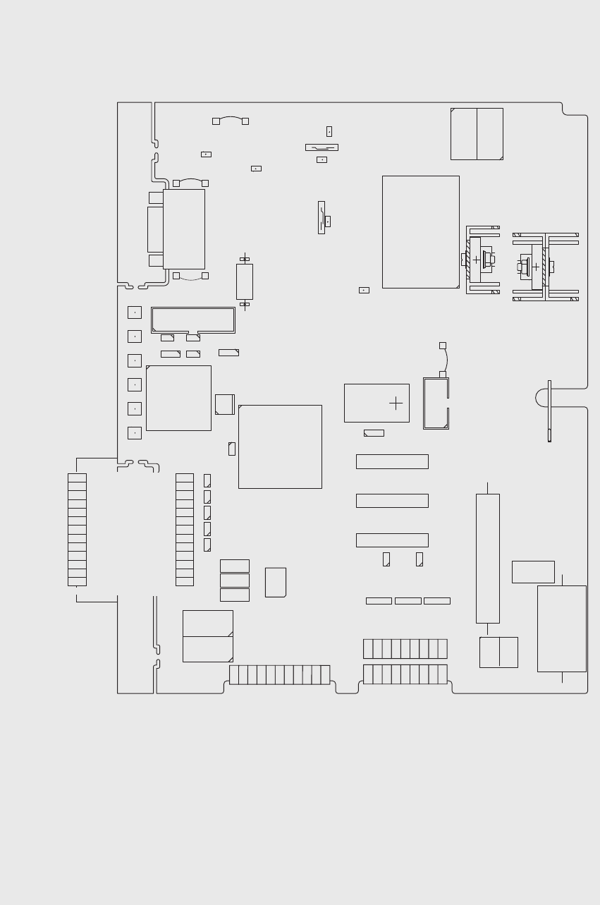
4.14 COMPONENT MOUNTING DIAGRAM CONTROL DEVICE
FIG. 10 FILE COMPONENT MOUNTING DIAGRAM CONTROL DEVICE