43
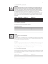
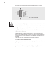
TERMINAL STRIP X5 IN THE CONTROL DEVICE
X5.1 FUNCTION X5.2 FUNCTION
5 +5V 5 +5V
13 ground 5V 10 set point 1
13 ground 5V 11 set point 2
13 ground 5V 32 analog output 1
13 ground 5V 33 analog output 2
13 ground 5V 34 analog output 3
13 ground 5V 16 ASM input
21 -15V 17 GSE connection
14 ground 24V 12 RESET
14 ground 24V 15 controller lock
14 ground 24V 18 SYT9 connection
14 ground 24V 19 QUIT
20 +24V* 20 +24V*
* Loading: I
X5.1.20
+ I
X5.2.20
+ I
X21.9
ͨ max. 80mA
TAB. 19 TERMINAL STRIP X5
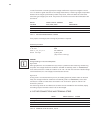
Terminal strip X6 in the control device
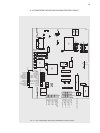
At the terminal strip X6, wiring between the control device A70 and the control cards A1, A3 and
A5 of the power section is performed by the works. Allocation of the terminal strip is as follows:
X6 Name
11 thyristor L1 neg.
12 +5V
13 thyristor L1 pos.
21 thyristor L2 neg.
22 +5V
23 thyristor L2 pos.
31 thyristor L3 neg.
32 +5V
33 thyristor L3 pos.
41 input temperature sensor
42 ground temperature sensor
TAB. 20 TERMINAL STRIP X6
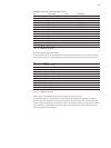
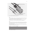
Each thyristor is controlled by 20mA current supply switching to ground.
The ventilator monitor is connected to the terminals X6.41 and X6.42 in separately ventilated
devices (..HF). The temperature of the power section is monitored using a PT 1000 temperature
sensor. In case of overheating of the power section, for instance caused by outage of the ventilator,
a fault indication is generated and the alarm relay is activated (default values). The temperature
may be enquired by the interfaces.


