


52
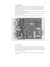
After switching on Thyro-P, it will automatically detect the Profi bus slot card. On the Thyro-P side,
the device address must be set using the LBA or Thyro-Tool Familiy.
After confi guration of the Profi bus, Thyro-P is ready for operation on the Profi bus.
CONNECTION TO THE PROFIBUS
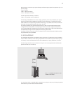
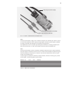
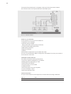
The Profi bus is connected to the 9-pin SUB-D socket X20. The usual plug (see table) or an OLP
module (fi bre optic) may be used for this.
The following plugs are recommended
ORDER NO. DESCRIPTION:
(SIEMENS)
6ES7 972-0BA40-0XA0 35° cable outlet including terminating resistors
6ES7 972-0BA30-0XA0 30° cable outlet without terminating resistors
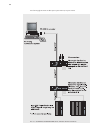
For connection of the OLP modules (Profi bus via fi bre optic), a 5V power supply voltage is provided
on the Profi bus socket X20, pin 6. This bears a load of at max. 80mA.
TERMINATING RESISTORS
Within a Profi bus segment, terminating resistors must be switched in the fi rst and the last device.
Because the Profi bus slot card does not have internal terminating resistors, plugs containing inte-
grated terminating resistors must be used and these must be switched on, if the fi rst or last device
is a Thyro-P!
REMARK
FAILURE OF THYRO-P OR PROFIBUS
If the Profi bus fails during operation of Thyro-P, set points or actual values cease to be transmitted.
Thyro-P continues to operate using the last current set point. If the Thyro-P fails as Profi bus slave,
then this fault is signaled on the Profi bus system. If the RESET function on Thyro-P is activated,
there will also be a RESET period the Bus function is interrupted.
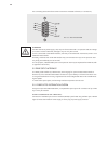
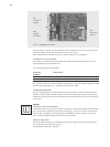
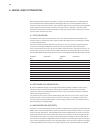
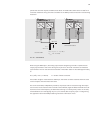
Additional digital inputs
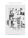
On the 9-pin SUB-D plug X21, the Profi bus slot card has four digital inputs which are mapped to
the 1st data byte of the reply from Thyro-P.
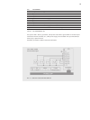
Pin assignment of the plug is as follows:
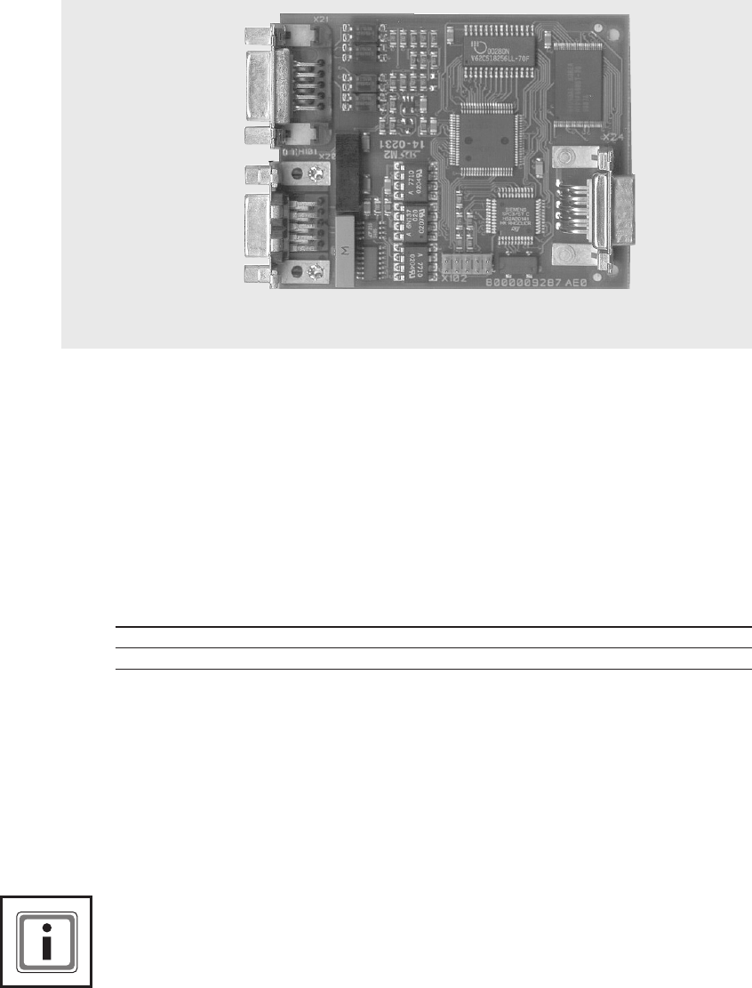
X21
4 inputs for
Profibus
X20
Profibus
connection
X24
connection
Thyro-P
LED
FIG. 16 PROFIBUS SLOT CARD