47
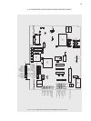
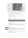
With the Power Controller Thyro-P, the following interfaces may be used for this (see also fi g. 11 on
previous page):
• X10, RS 232
• X30, fi bre optic receiver
• X31, fi bre optic transmitter
as well as optional interfaces, for instance
• X20, bus interface, e.g. for Profi bus DP
All internally processed data like current, voltage, power, set point value, limitations, etc. may be
enquired, processed and modifi ed during operation (online operation) in master-slave process.
Under assistance of corresponding automation technology, it is possible to do without connection
of process controls, potentiometers, instruments, LBA, etc.
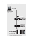
The existing interfaces may operated simultaneously, so that for instance the following system
confi guration would be possible: a stored-program control via Profi bus supplies the set points,
a PC visualizes (fi bre optic interface/Thyro-Tool Familiy) the data and on location the device status
and selected operating values are displayed via LBA (using the RS 232).
Therefore, the Power Controller Thyro-P is transparent to all levels of production and the process
may therefore be securely handled.
5.1 RS 232 INTERFACE
The isolated RS 232 interface is provided for direct connection of an LBA (with cabinet installation
kit also indirect via cable) or a PC. Setting of parameters of the interface is performed using Thyro-
Tool Familiy or LBA. The default baud rate is set to 9600 baud, no parity, 8 data bits, 1 stop bit.
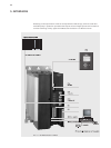
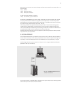
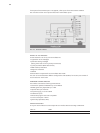
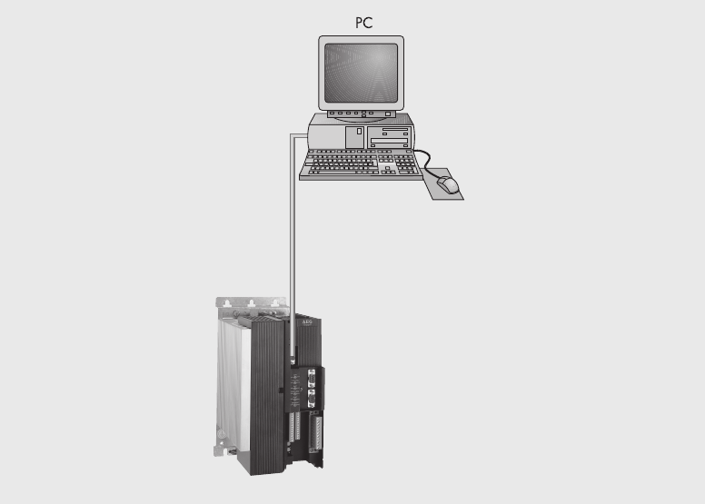
The following illustration shows connection of a Thyro-P to a PC using the RS 232 interface (also
possible via fi bre optic or Profi bus).
For connecting the PC, an RS 232 cable is required. On the Thyro-P side, a 9-pin sub-D plug and on
the PC side a 9-pin sub-D socket must be available.
FIG. 12 CONNECTION OF A PC TO
THYRO-P VIA RS 232
RS 232
COM 1
or
COM 2


