61
8.1 INSTALLATION
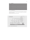
The installation orientation of Thyro-P is vertical, so that ventilation of the thyristors fastened to
heat sinks is ensured. In case of cabinet mounting, additionally suffi cient ventilation of the cabi-
net must be ensured. The distance between Power Controller and the bottom should be at least
100mm; the distance to the ceiling 150mm. The devices may be installed next to each other with-
out lateral distance. Heating up of the device by heat sources must be avoided. The dissipation of
the Power Controller is stated in the table chapter type overview.
Grounding must be performed according to local regulations of the utility company (grounding
screw for protective conductor connection).
8.2 COMMISSIONING
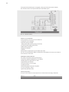
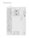
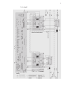
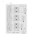
The device must be connected to the mains and the associated load according to the wiring
diagrams.
REMARK
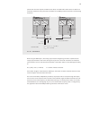
It must be observed that with 1P, terminal A1 X1:3 is connected to the U2 on the opposite load
side. With 2P it must be observed that terminal A1 X1:3 is connected to the non-controlled phase.
Depending on connection system of the load (star, delta, etc.), it must be ensured that the load vol-
tage transformers in the power sections are wired correctly (terminal strip X1 of the power section).
The correct terminals may be found in the connecting diagrams.
If the units 1P and 2P are operated at over 600 V and without load at the output side, voltages can
occur above input voltage at the connection points U2 and W2. In this case, an additional 690 V
damping card is to be used. (Section 12, Accessories and Options)
On delivery, the device is parameterized adjusted to the respective power section. The operating
mode TAKT is set. If a different operating mode is desired, then the user must set this using the
LBA, PC, etc. Generally, the standard parameters (see menu list) should be reviewed and adjusted
to the respective conditions for use by the user (for instance operating mode, control mode, limi-
tations, monitoring, times, characteristics, actual value outputs, fault indications, relays, time and
date, etc.).
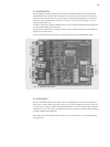
Besides the load, some control signals must be connected as well (refer to chapter 4). The following
signals are always required for operation of the device:
Set point (terminal 10 or 11/or via interfaces)
RESET (on ground, on terminal 12, jumper set as standard)
Regular inhibit (on ground, on terminal 15, jumper set as standard)
If the RESET is not connected, then the device is in reset state and is not operating (LED „ON“
shows red light), i.e. no communications is possible via interface. Further details of the RESET are
described in chapter 4.4. If the regulator inhibit is not connected, then the device is fully operable,
but the power section is only controlled using the values of the minimal limitations (LED „PULSE
LOCK“ is on). Further details on the regulator inhibit may be found in the chapter 4.5 of the same
name.
8. SPECIAL REMARKS


