40
4.6 QUIT
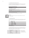
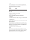
The input acknowledge (Quit, X5.2.19) has a circuit identical with the input RESET. It must be
short-circuited against ground (X5.1.14) so that any faults are acknowledged. The fault signalling
relay is reset. The input must remain closed for at least 2 line periods to perform acknowledgement.
After acknowledgement, the contactor must in turn be opened.
Function:
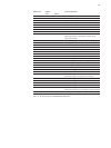
TERMINALS FUNCTION
X5.19-14 open controller operating
X5.19-14 closed* faults are reset
* for at least 2 line periods
TAB. 14 QUIT
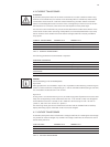
If the QUIT contact is reopened the Controller will reassume operation with its preset operating
and control modes as well as its set point and limiting values.
4.7 SET POINT VALUE INPUTS
The set point inputs are described in chapter 2.2. Set point control characteristic.
4.8 ASM INPUT
This input (analog voltage signal) serves to measure the total current signal of the external apparent
ohmic resistance. For further information refer to chapter ”ASM procedure“.
4.9 ANALOG OUTPUTS
The electrical values for current, voltage and power at the load as well as the set point are recorded
by the Power Controller Thyro-P and may be optionally displayed using an external instrument or
logged using a graph recorder.
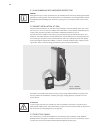
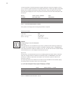
For connection of external instruments, there are three actual value outputs (terminals X5.2.32,
X5.2.33, X5.2.34, against X5.1.13). The selectable signal levels are 0-10 volts, 0-20mA, 4-20mA or -
setting different parameters at a maximum compliance voltage of 10V. In case of active ASM proce-
dure, only two of these three analog outputs are freely available (terminal X5.2.32, X5.2.34).
Each output has its own D/A converter. By setting parameters, it is possible to adjust the outputs
to stored-program controls, measuring instruments, etc.
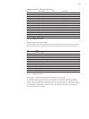
For instance, the following values may be output:
• currents, voltages or power of the individual phases, total power
• minimum or maximum values
• set points
• phase angles
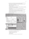
The signals of the analog outputs are updated in each line (VAR) or TAKT period. Actual values
always relate to the previous period. In operation mode VAR at a net period (e.g. 50Hz:20ms) and
in operation mode TAKT at T0 (e.g. 1 sec.). Different factors (e.g. set point variations, load varia-
tions, limitings and the infl uence of operating modes with SSSD and MOSI) give the actual value
signals dynamic rations which can be smoothed with a smoothing stage. The MEAN (VALUE) para-
meter is applied here. The following setting is recommended: MEAN(VALUE) = 25.


